RM0402 Rev 6 353/1163
RM0402 Digital filter for sigma delta modulators (DFSDM)
400
14.4.3 DFSDM reset and clocks
DFSDM on-off control
The DFSDM interface is globally enabled by setting DFSDMEN=1 in the
DFSDM_CH0CFGR1 register. Once DFSDM is globally enabled, all input channels (y=0..3)
and digital filters DFSDM_FLTx (x=0..1) start to work if their enable bits are set (channel
enable bit CHEN in DFSDM_CHyCFGR1 and DFSDM_FLTx enable bit DFEN in
DFSDM_FLTxCR1).
Digital filter x DFSDM_FLTx (x=0..1) is enabled by setting DFEN=1 in the
DFSDM_FLTxCR1 register. Once DFSDM_FLTx is enabled (DFEN=1), both Sinc
x
digital
filter unit and integrator unit are reinitialized.
By clearing DFEN, any conversion which may be in progress is immediately stopped and
DFSDM_FLTx is put into stop mode. All register settings remain unchanged except
DFSDM_FLTxAWSR and DFSDM_FLTxISR (which are reset).
Channel y (y=0..3) is enabled by setting CHEN=1 in the DFSDM_CHyCFGR1 register.
Once the channel is enabled, it receives serial data from the external Σ∆ modulator or
parallel internal data sources (CPU/DMA wire from memory).
DFSDM must be globally disabled (by DFSDMEN=0 in DFSDM_CH0CFGR1) before
stopping the system clock to enter in the STOP mode of the device.
DFSDM clocks
The internal DFSDM clock f
DFSDMCLK
, which is used to drive the channel transceivers,
digital processing blocks (digital filter, integrator) and next additional blocks (analog
watchdog, short-circuit detector, extremes detector, control block) is generated by the RCC
block and is derived from the system clock SYSCLK or peripheral clock PCLK2 (see
Section 6.3.24: RCC Dedicated Clocks Configuration Register (RCC_DCKCFGR)). The
DFSDM clock is automatically stopped in stop mode (if DFEN = 0 for all DFSDM_FLTx,
x=0..1).
The DFSDM serial channel transceivers can receive an external serial clock to sample an
external serial data stream. The internal DFSDM clock must be at least 4 times faster than
the external serial clock if standard SPI coding is used, and 6 times faster than the external
serial clock if Manchester coding is used.
DFSDM can provide one external output clock signal to drive external Σ∆ modulator(s) clock
input(s). It is provided on CKOUT pin. This output clock signal must be in the range
specified in given device datasheet and is derived from DFSDM clock or from audio clock
(see CKOUTSRC bit in DFSDM_CH0CFGR1 register) by programmable divider in the
range 2 - 256 (CKOUTDIV in DFSDM_CH0CFGR1 register). Audio clock source is SAI1
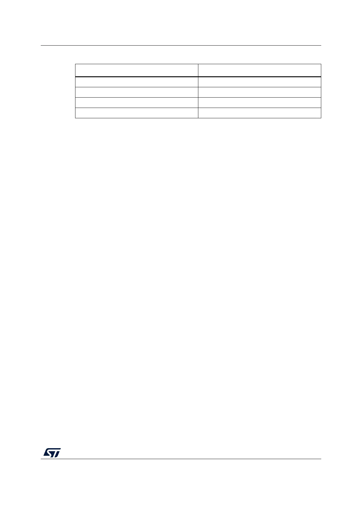
Table 87. DFSDM break connection
Break name Break destination
dfsdm_break[0] TIM1 break
dfsdm_break[1] -
dfsdm_break[2] TIM8 break
dfsdm_break[3] -