RM0402 Rev 6 97/1163
RM0402 Power controller (PWR)
108
5.3.5 Stop mode
The Stop mode is based on the Cortex
®
-M4 with FPU deepsleep mode combined with
peripheral clock gating. The voltage regulator can be configured either in normal or low-
power mode. In Stop mode, all clocks in the 1.2
V domain are stopped, the PLLs, the HSI
and the HSE RC oscillators are disabled. Internal SRAM and register contents are
preserved.
Some settings in the PWR_CR register allow to further reduce the power consumption.
When the Flash memory is in power-down mode, an additional startup delay is incurred
when waking up from Stop mode (see
Table 20: Stop operating modes and Section 5.4.1:
PWR power control register (PWR_CR)).
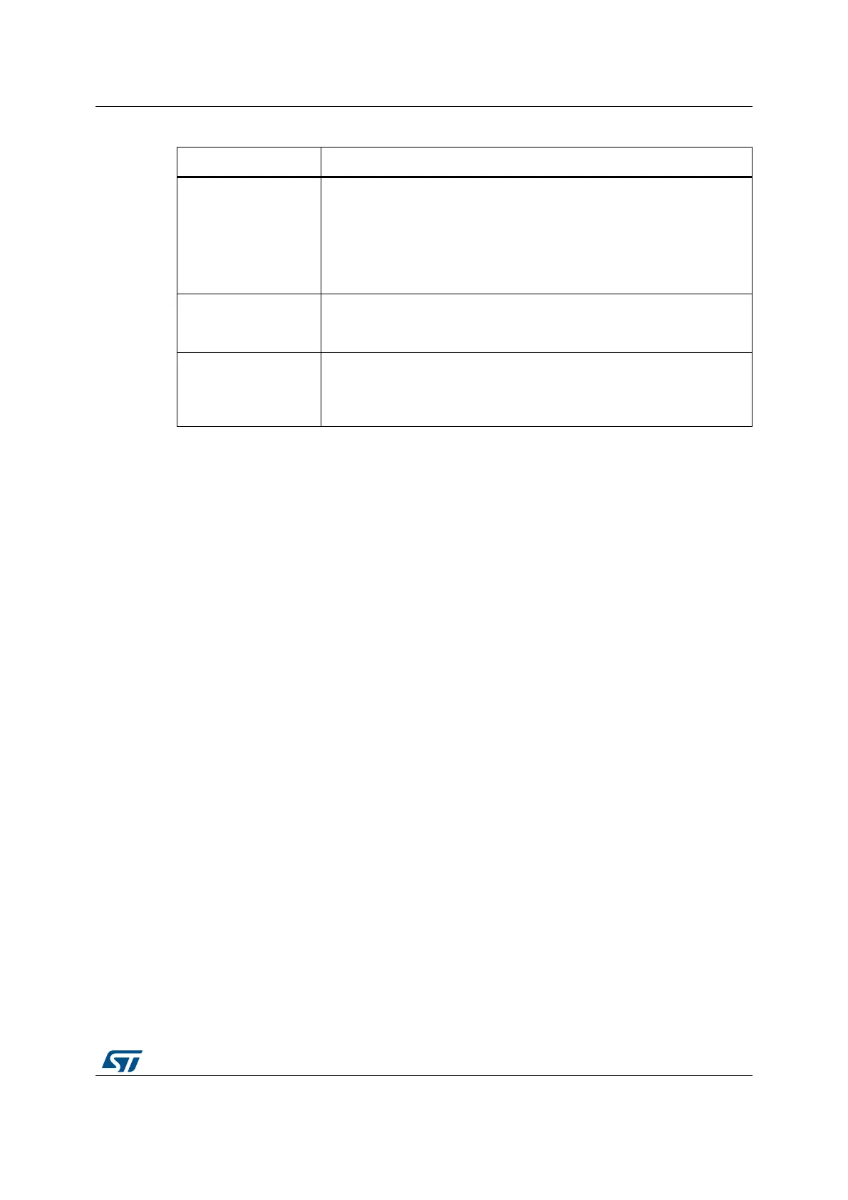
Table 19. BAM-on-exit entry and exit
Sleep-on-exit Description
Mode entry
Set the Flash memory in low-power mode:
– FISSR/FMSSR and FPDS bits of the PWR_CR register
WFI (wait for interrupt) while:
– SLEEPDEEP = 0 and
– SLEEPONEXIT = 1
Refer to the Cortex
®
-M4 with FPU System Control register.
Mode exit
Interrupt: refer to Table 40: Vector table for STM32F412xx
If Flash memory wakeup time is needed, FISSR/FMSSR bits of PWR_CR
register must be set
Wakeup latency
None when code executed from internal SRAM
Low-power mode Flash memory wakeup time, before restarting code
execution from Flash memory (refer to the Flash memory wakeup time in
the Electrical characteristics section of the datasheet).