18 Operations Water Management functionality
c. Select the benchmark to be used as a the pivot for the new slope from the screen.
d. Tap OK. The Plane Editor screen displays.
7.
Select the Primary Slope, Cross Slope, or Height Above Pivot areas to edit the slope values as
required.
Note – The cut/fill values in the Benchmarks table will update automatically.
8.
The plane is now defined. Tap OK. The Run screen displays.
Note – The FieldLevel II system will search for a survey on the field. If there is a survey, a cut/fill map
displays as the new design plane.
Contour mode
1. At the Run screen, drive the vehicle to the location where you want to start the first levee.
2. Set the master benchmark at this point.
3. Set which side of the vehicle is uphill.
4. Tap Guide and drive the vehicle forward, following the lightbar to keep the vehicle on the same
contour.
a.
To move to the next levee, turn the vehicle around and change the Up Hill direction.
b. To step the blade up or down, use the and plus and minus buttons to achieve the required
offset and then follow the lightbar to keep the correct grade.
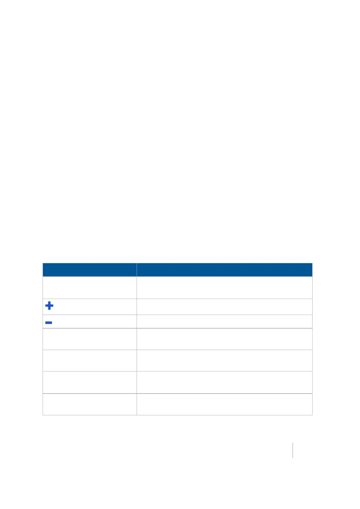
When you drive in Point and Slope mode, the FieldLevel IIpanel displays these controls.
Button Explanation
Coarse
/
Fine
Coarse: The blade will move by large increments.
Fine:The blade will move by small increments.
Raises the blade by the fine or coarse increment.
Lowers the blade by the fine or coarse increment.
Up Hill Left
Select if you are driving around the contour with the uphill
slope on your left and the downhill slope on your right.
Up Hill Right
Select if you are driving around the contour with the uphill
slope on your right and the downhill slope on your left.
Bench
or
Re-Bench
Tap to create a benchmark or re-bench.
Set the Design Height equal to the Blade Height.
Delete Benchmark
Removes any benchmark on the field. You do not need to
drive over a benchmark to delete it.
Version 9.25, Revision B FM-1000 Integrated Display User Guide 443