EasyManua.ls Logo

Delta ASDA-A2 User Manual

Delta ASDA-A2
721 pages
To Next Page IconTo Next Page
To Previous Page IconTo Previous Page
Page #430 background imageLoading...
Page #430 background image
ASDA-A2 Chapter 8 Parameters
Revision February, 2017 8-179
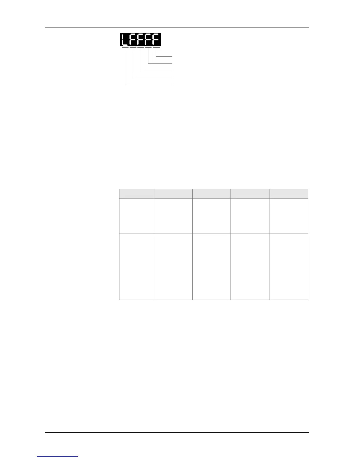
Settings
X
Y
Z
U
Low word
X: See the following table
Y: 0CAPTURE is not working
1AUX ENC (linear scale) is set as the source
2PULSE Cmd
3Main ENC (main encoder)
When the source of CMP is CAP axis, the source Y of CAP cannot
be changed.
Z: 0NO, 1NC
U: trigger the minimum interval (Unit: ms)
bit 3 2 1 0
X function Execute PR
when
finishing
capturing
After
capturing the
first data,
CMP is
activated.
Reset the
position of
the first data
Activate CAP
Description Execute PR
50 after
finishing CAP
It is invalid
when CMP is
activated.
After
capturing the
first data,
reset the
position
coordinate
Starts to
capture when
it is set to 1.
After
finishing
capturing,
this bit
becomes 0
automatically
.
bit 0: When the value set by P5-38 is bigger than 0, set bit 0 to 1 will
activate CAP function and DO.CAP_OK is OFF. Every time,
when a data is captured, the value of P5-38 will minus one. When
the P5-38 is 0, it means the capture function is completed,
DO.CAP_OK is ON and bit 0 will be reset to 0 automatically. If
P5-38 equals to 0, set bit 0 to 1 will not activate CAP function.
DO.CAP_OK is OFF and bit 0 will automatically be set to 0. If
CAP function is activated, it cannot set 1 to bit 0. It only can be
written 0 to disable CAP function.
bit 1: If this bit is 1, when capturing the first data, the current position of
CAP axis will be set to the value of P5-76.
bit 2: If this bit is 1, when capturing the first data, CMP will be activated.
(When bit 0 of P5-59 is set to 1 and P5-58 is set to the previous
value.) If CMP has been activated, then this function is invalid.
bit 3: If this bit is 1, as soon as the CAP finished, PR procedure #50 will
be triggered automatically.

Table of Contents

Other manuals for Delta ASDA-A2

Question and Answer IconNeed help?

Do you have a question about the Delta ASDA-A2 and is the answer not in the manual?

Delta ASDA-A2 Specifications

General IconGeneral
Control ModePosition, Speed, Torque
ModelASDA-A2 Series
Operating Voltage200 ~ 230VAC / 380 ~ 480VAC
Power Supply200-230VAC ±10%, single-phase
Communication InterfaceRS-485, CANopen
FeedbackIncremental encoder, Absolute encoder
ProtectionOvercurrent, Overvoltage, Undervoltage, Overheating, Short Circuit
Operating Temperature0°C
Storage Temperature-20°C
Humidity20% to 90% RH (non-condensing)
Position Control Mode FeaturesElectronic Cam
WeightVaries depending on the model. Please refer to the specific model's datasheet.

Summary

Preface

Safety Precautions

Highlights potential hazards and prohibited activities during operation, installation, and wiring.

Chapter 3 Wiring

3.4 I/O Signal (CN1) Connection

Details the terminal layout and signal descriptions for the CN1 connector.

Chapter 4 Panel Display and Operation

4.2 Parameter Setting Procedure

Outlines the steps for switching modes and operating within Monitor, Parameter, and Alarm modes.

4.4 General Function

Covers operations like fault record display, JOG mode, forced DO output, and digital input/output diagnosis.

Chapter 5 Trial Operation and Tuning

5.1 Inspection without Load

Provides checks before operation and after applying power, focusing on safety and wiring.

5.2 Applying Power to the Servo Drive

Instructions on correctly wiring the motor and applying power, including checks for 220V and 400V drives.

5.6 Tuning Procedure

Guides on estimating inertia ratio using JOG mode and tuning procedures like auto and semi-auto tuning.

Chapter 6 Control Mode of Operation

6.1 Selection of Operation Mode

Lists and describes single and dual control modes: Position, Speed, Torque, and CANopen.

6.2 Position Mode

Details the settings and related information for Position Mode, including PT and PR commands.

6.3 Speed Mode

Explains speed control modes (S, Sz) with analog and register inputs, including S-curve and gain adjustments.

6.4 Torque Mode

Details torque control modes (T, Tz) with analog input and register command sources.

Chapter 7 Motion Control

7.9 DI / DO Provided by PR Mode and Diagrams

Lists DI signals (CTRG, SHOM, STP, etc.) and DO signals (CMD_OK, MC_OK, TPOS, etc.) used in PR mode.

7.10 Parameter Settings

Details parameters for target speed, acceleration/deceleration time, pause time, and PR mode settings.

7.11 The Description of E-Cam Function

Explains E-Cam as a virtual cam, comparing it with machine cams and detailing features.

Chapter 8 Parameters

8.2 List of Parameters

Provides a comprehensive list of parameters, their functions, default values, and related sections.

8.3 Parameter Description

Detailed descriptions of P0-xx Monitor Parameters, including firmware version and alarm codes.

Chapter 9 Communications

9.1 RS-485 & RS-232 Communication Hardware Interface

Explains the hardware interface for RS-485 and RS-232 communication.

9.2 RS-485 / RS-232 Communication Parameters Setting

Details essential parameters like Address Setting, Transmission Speed, Protocol, and Mechanism.

9.3 MODBUS Communication Protocol

Describes MODBUS communication modes (ASCII, RTU) and character structure.

9.4 Write-in and Read-out Communication Parameters

Covers parameters that can be written or read via communication and provides notes on their usage.

Chapter 10 Troubleshooting

10.1 Alarm of Servo Drive

Lists common servo drive alarms, their descriptions, corresponding DO, and servo status.

10.2 Alarm of CANopen Communication

Details CANopen communication alarms, including SDO Rx Buffer overflow, PDO Rx Buffer overflow, and Index errors.

10.3 Alarm of Motion Control

Lists alarms related to motion control, such as CANopen data loading errors and PR parameter range issues.

10.4 Causes and Corrective Actions

Provides a table of common causes, checking methods, and corrective actions for various servo drive alarms.

10.5 Corrective Actions after the Alarm Occurs

Offers corrective actions for specific alarms like Over current, Over voltage, and Encoder errors.

Chapter 11 Specifications

Chapter 12 Absolute System

12.3 System Initialization Procedure and Operation

Details system initialization steps, including homing and parameter settings.

12.7 Alarms for Absolute System

Lists absolute system alarms, their descriptions, and corrective actions.

Appendix B Maintenance and Inspection

Inspection Before Operation

Pre-operation checks before power application and before running the servo drive.

Related product manuals