501-16-6 Wipers and Washers 501-16-6
DIAGNOSIS AND TESTING (CONTINUED)
CONDITIONS
DETAILS/RESULTS/ACTIONS
A4: CHECK THE POWER SUPPLY OF FUSE F12
1.
Fuse F12 (CJB)
2.
3 Measure the voltage between fuse F12 (20 A)
and ground.
• Is battery voltage indicated?
Yes
GO TO A5
No
CHECK the CJB. If necessary INSTALL a
new one. TEST the system for normal op-
eration.
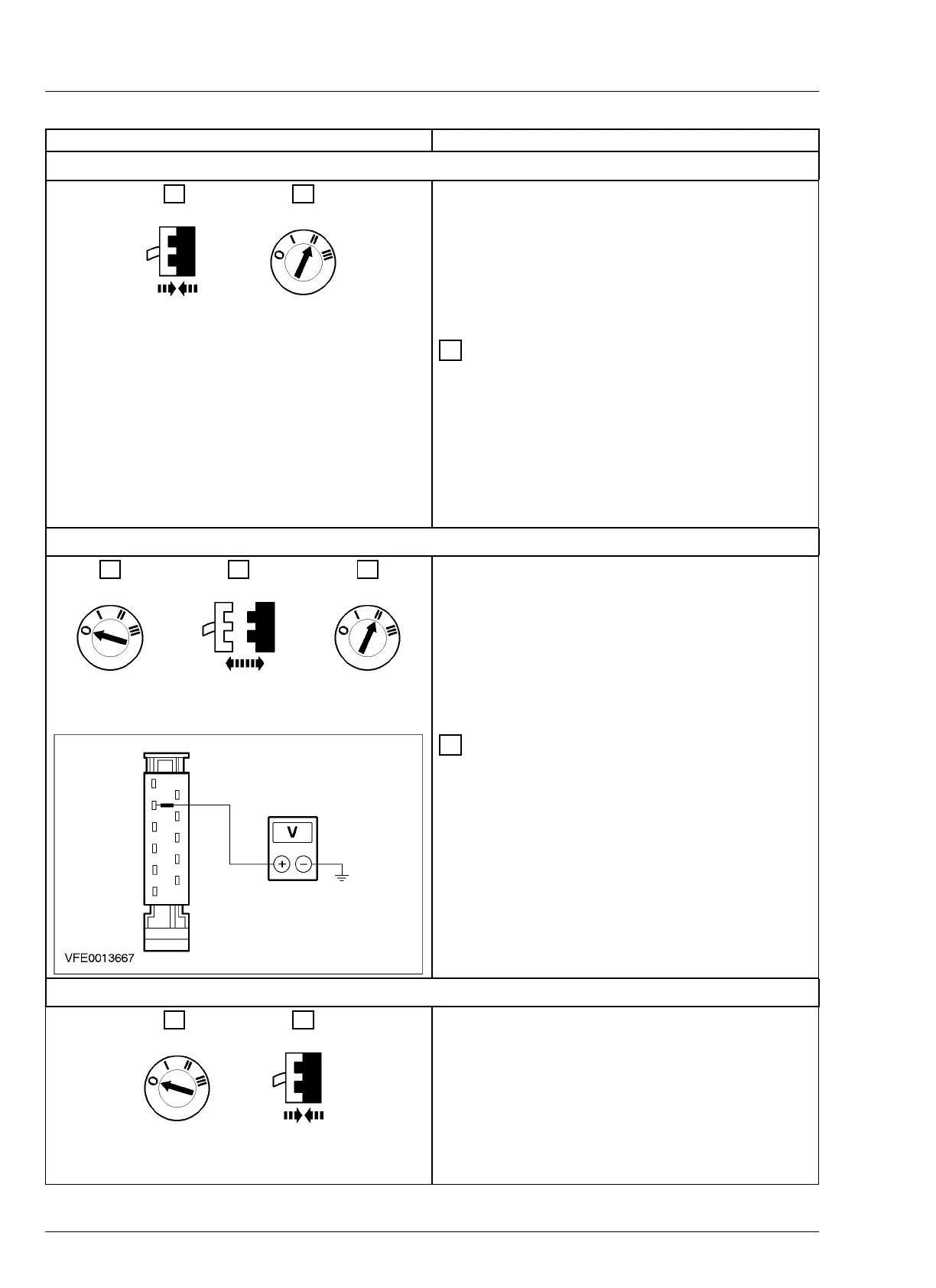
A5: CHECK THE POWER SUPPLY OF MULTIFUNCTION SWITCH
1.
2.
Multifunction switch
C15b
3.
4 Measure the voltage between multifunction
switch, connector C15b, pin 7, circuit 14-AK19
(VT/OG), harness side and ground.
• Is battery voltage indicated?
Yes
GO TO A6
No
REPAIR the power supply of multifunction
switch, by using the wiring diagrams. TEST
the system for normal operation.
A6: CHECK THE MULTIFUNCTION SWITCH FOR PROPER FUNCTION
1.
2.
Multifunction switch
C15b
E9432 EN 07/2001 2002 Bantam



 To Next Page