MPC5604B/C Microcontroller Reference Manual, Rev. 8
420 Freescale Semiconductor
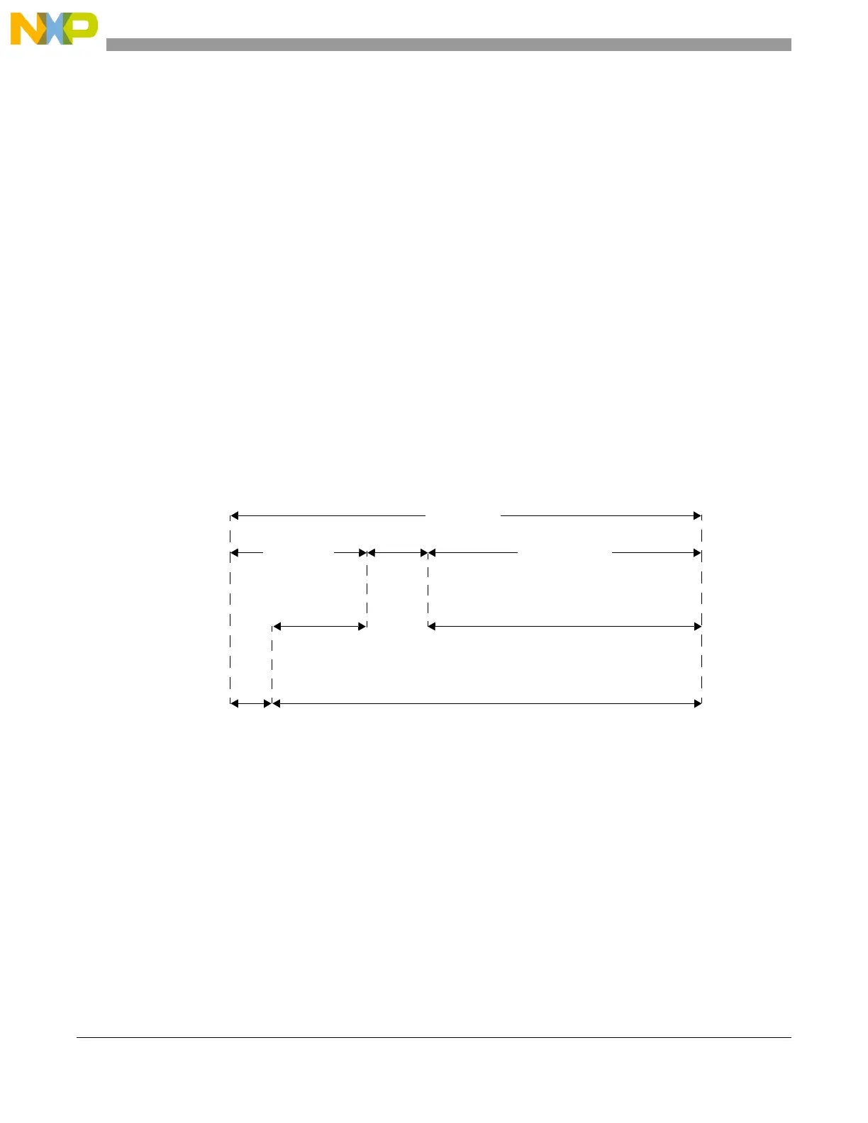
21.8.3.1.2 LIN Slave mode
The LINTOCR[RTO] field can be used to tune response timeout and frame timeout values. Header timeout
value is fixed to HTO.
OC1 checks T
Header
and T
Response
and OC2 checks T
Frame
(see Figure 21-32).
When LINFlex moves from Break state to Break Delimiter state (see Section 21.7.1.3, LIN status register
(LINSR)):
• OC1 is updated with the value of OC
Header
(OC
Header
=CNT+HTO),
• OC2 is updated with the value of OC
Frame
(OC
Frame
=CNT+HTO +RTO×9 (frame timeout
value for an 8-byte frame)),
• The TOCE bit is set.
On the start bit of the first response data byte (and if no error occurred during the header reception), OC1
is updated with the value of OC
Response
(OC
Response
= CNT + RTO × 9 (response timeout value for an
8-byte frame)).
Once the first response byte is received, OC1 and OC2 are automatically updated to check T
Response
and
T
Frame
according to RTO (tolerance) and DFL.
On the checksum reception or in case of error in the header or data field, the TOCE bit is reset.
Figure 21-32. Header and response timeout
21.8.3.2 Output compare mode
Programming LINTCSR[LTOM] = 0 enables the output compare mode. This mode allows the user to fully
customize the use of the counter.
OC1 and OC2 output compare values can be updated in the LINTOCR by software.
OC
Frame
OC
Header
OC
Response
Header
Response
Break
Frame
OC1
OC2
Response
space
 Loading...