WindO/I-NV4 User’s Manual 35-27
2 HG5G/4G/3G/2G-V
35
MICRO/I Specifications
● HG5G/4G/3G/2G-V Installation
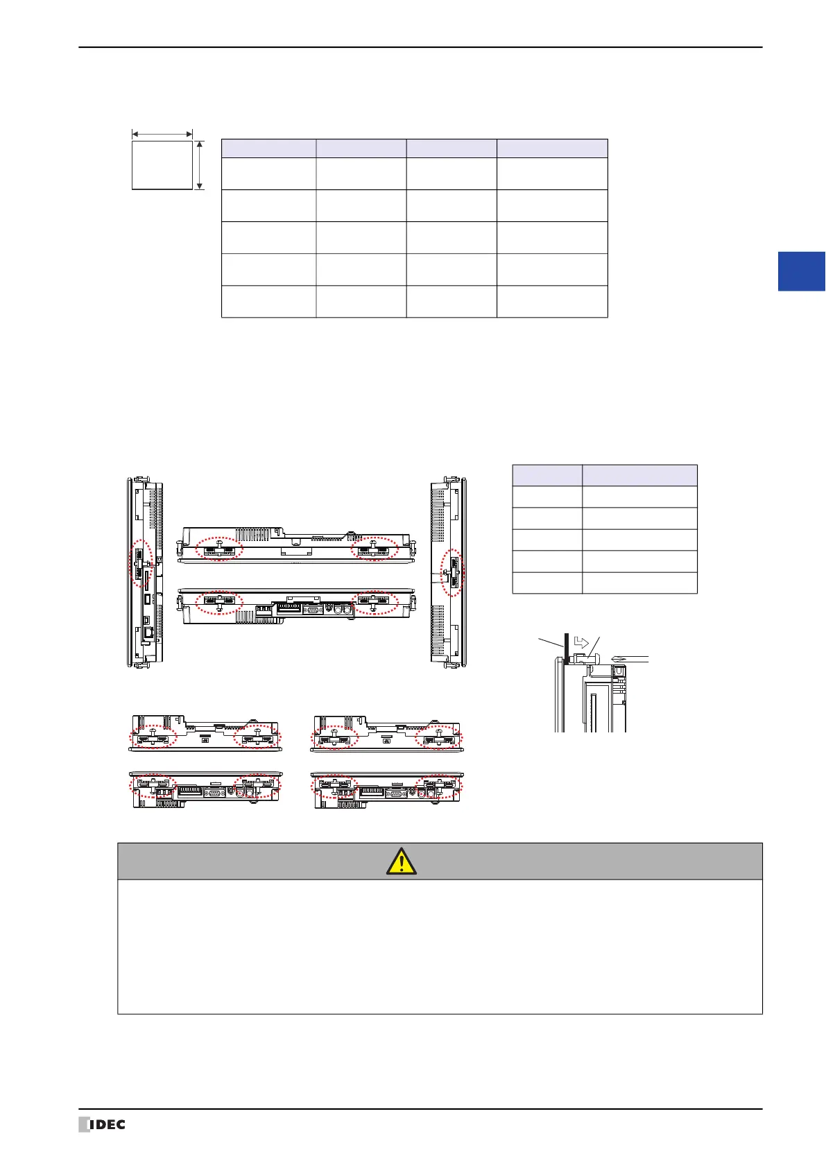
• Make a panel cut-out on the panel with the dimensions shown below.
• Install the HG5G/4G/3G/2G-V in a panel cut per the chart above. As it is the following figure, fasten the mounting
clips on the top, bottom, and sides of the unit to secure to the panel.
When mounting the HG5G/4G/3G/2G-V was installed in the part besides the following figure, it may not satisfy
product specifications such as waterproof performance, shock resistance and vibration resistance performance.
Mounting Clip Position
CAUTION
• Do not tighten with excessive force, otherwise the HG5G/4G/3G/2G-V may warp and cause
wrinkle on the display, or impair the waterproof characteristics.
• If the mounting clips are tightened obliquely to the panel, the HG5G/4G/3G/2G-V may fall off the
panel.
• When installing the HG5G/4G/3G/2G-V into a panel cut-out, make sure that the gasket is not
twisted. Especially when re-installing, take special care because any twists in the gasket will
impair the waterproof characteristics.
Unit: mm
Type No. A B Panel Thickness
HG5G-V 279.0
+2.0
0
352.0
+2.0
0
2.0 to 5.0
HG4G-V 227.5
+2.0
0
301.5
+2.0
0
2.0 to 5.0
HG3G-VA 200.0
+2.0
0
258.0
+2.0
0
2.0 to 5.0
HG3G-V8 164.0
+2.0
0
219.0
+2.0
0
2.0 to 5.0
HG2G-V 121.0
+2.0
0
153.0
+2.0
0
1.6 to 5.0
Unit : N∙m
Type Specified Torque
HG5G-V 0.5 to 0.6
HG4G-V 0.5 to 0.6
HG3G-VA 0.5 to 0.6
HG3G-V8 0.5 to 0.6
HG2G-V 0.2 to 0.3
HG5G-V
HG4G/3G-V
BOTTOM
TOP
HG2G-V
Mounting
Clip
Panel
 Loading...