7 Alarm List Display
10-138 WindO/I-NV4 User’s Manual
7.3 Properties of Alarm List Display Dialog Box
This section describes items and buttons on the properties dialog box.
●
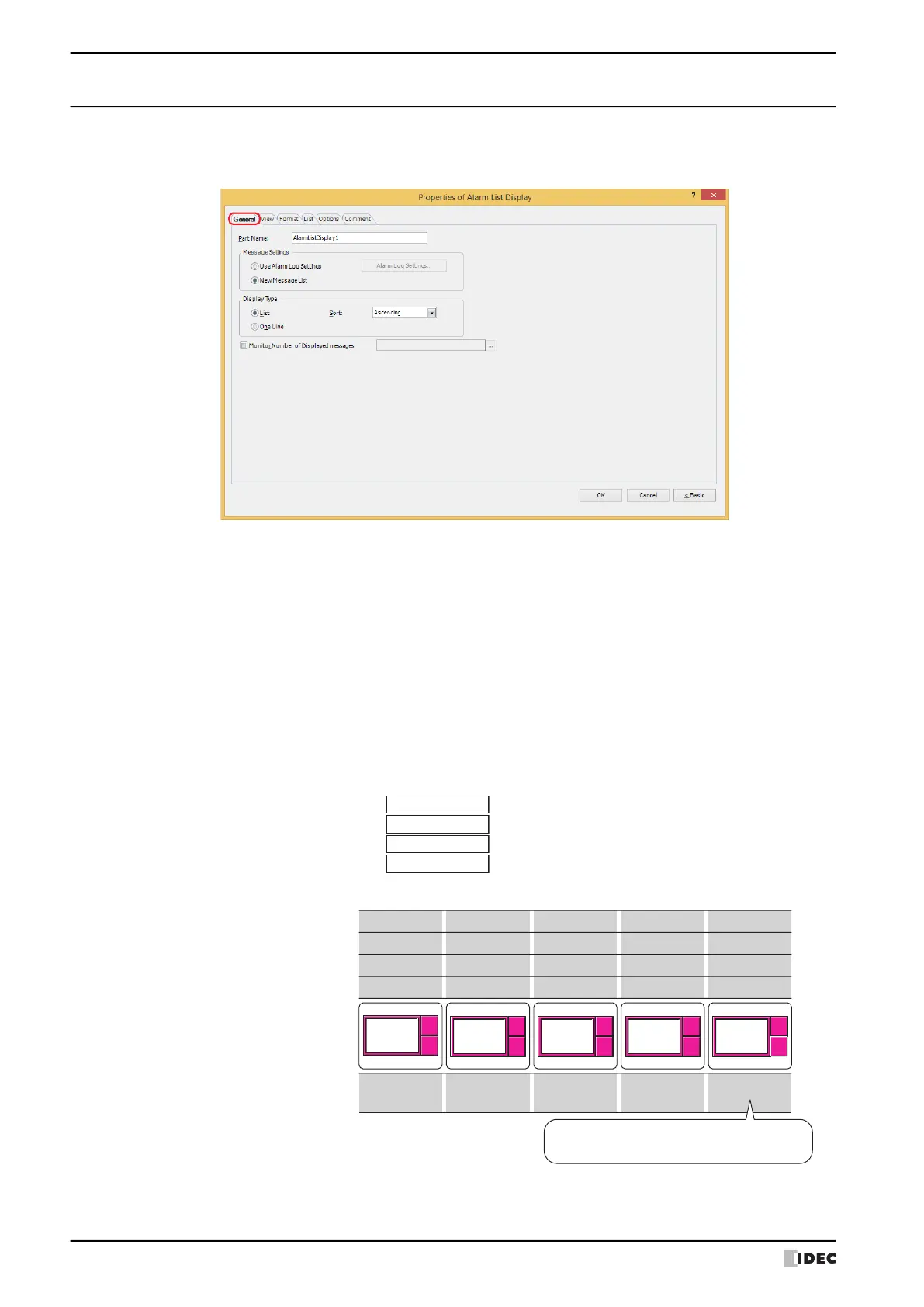
General Tab
■ Part Name
Enter a name for the part. The maximum number is 20 characters.
■ Message Settings
Selects the method for switching message to display.
The active alarm messages are displayed.
Use Alarm Log Settings: Displays messages for the active alarms. The alarms are configured by the Alarm Log
settings.
Alarm Log Settings: Displays the Alarm Log Settings dialog box.
New Message List: Displays the messages registered in Text Manager according to the state of bits in the
trigger device address configured on the List tab.
Example: When Use Alarm Log Settings is selected, the source device address (device address to monitor)
configured by the Alarm Log function is D0, and the following messages are allocated to the channels
D0-0 :
D0-1 :
D0-2 :
D0-3 :
ID1
Current fault
ID2
ID3
ID4
Pump fault
High pressure
Low air pressure
Message
Source device address
Message to display
Bit state of Source device address
D0-0
Display ID1
Action
Display ID2, ID3
1 0 1
1
0
D0-1
0 1 0
1
0
D0-2
0 1 1
1
0
D0-3
0 0 1
1
0
No message
Display ID1, ID2,
ID3, ID4
Display ID1, ID3,
ID4
Current fault
Pg. Up
Pg. Dwn
Pg. Up
Pg. Dwn
Pump fault
High pressure
Pg. Up
Pg. Dwn
Current fault
High pressure
Low air pressure
Pg. Up
Pg. Dwn
Current fault
Pump fault
High pressure
Low air pressure
Pg. Up
Pg. Dwn
If all bits in the device address are 0 or if a bit with no
associated message becomes 1, display nothing.