WindO/I-NV4 User’s Manual 13-5
1 Overview
13
Alarm Log Function
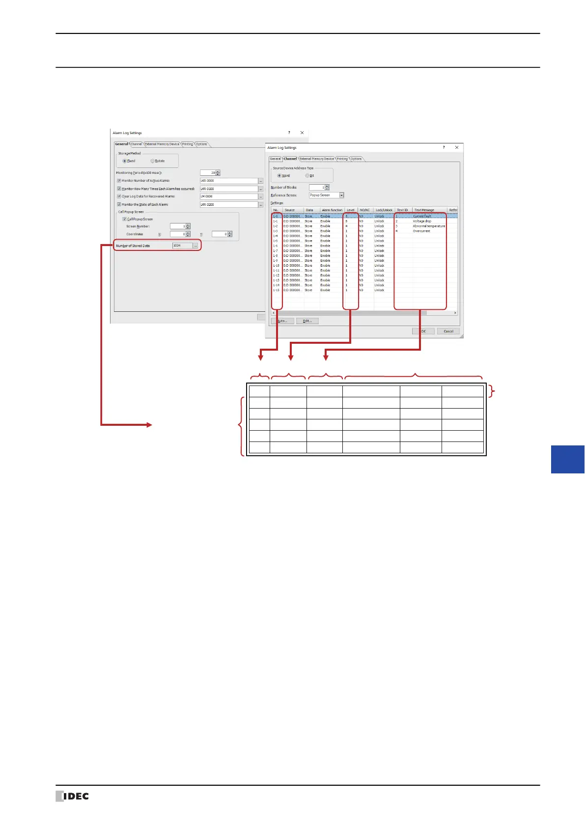
1.4 Data Configuration
The sampled data is composed of the channel number, level, message, alarm state, time, and label.
The relationship between the Alarm Log function settings and the sampled data is as follows.
1. Data storage amount: The amount of data that can be saved in the data storage area. For details, refer to “Data
Storage Amount” on page 13-8.
2. Channel No.: Composed of (Block No.)-(Channel No.). The device addresses to monitor and the
conditions for alarm occurrence and recovery are configured in the channels. When the
sampled data is output as a CSV file, the displayed label is “Ch.No.”.
3. Level: It is the level of alarm.
Can only output when the Output Alarm Level check box in the External Memory
Device tab on the Alarm Log Settings dialog box is selected.
4. Message: The message displayed when an alarm has occurred.
5. Alarm state and time: The alarm state (occurred, recovered, confirmed) and the time the alarm occurred, was
recovered from, and confirmed. When the sampled data is output as a CSV file, the
displayed label varies based on the output method.
6. Label: When the sampled data is output as a CSV file, this is the text displayed in the label row.
This cannot be changed.
Ch.No. Message Occurrence Time Recovery Time
Confirmation Time
1-1 Voltage drop 12/01/2011 12:00:05 12/01 12:01:10 12/01 12:01:30
1-2
Abnormal temperature
12/01/2011 12:01:09 12/01 12:02:21 12/01 12:02:55
1-1 Voltage drop 12/01/2011 12:02:00 12/01 12:03:11 12/01 12:05:12
1-3 Overcurrent 12/01/2011 12:30:21 12/01 12:55:15 12/01 13:00:00
1-1 Voltage drop 12/01/2011 12:45:36 12/01 12:53:12 12/01 12:57:41
Level
Level 8
Level 4
Level 8
Level 1
Level 8
1. Data storage amount
2. Channel No.
6. Label
3. Level 5. Alarm state and time4. Message
Sampled data
Alarm Log settings