WindO/I-NV4 User’s Manual 5-1
5
Screen
This chapter gives an overview of the MICRO/I screen and describes how to create setup and operate the screen.
1.1 Screen Types
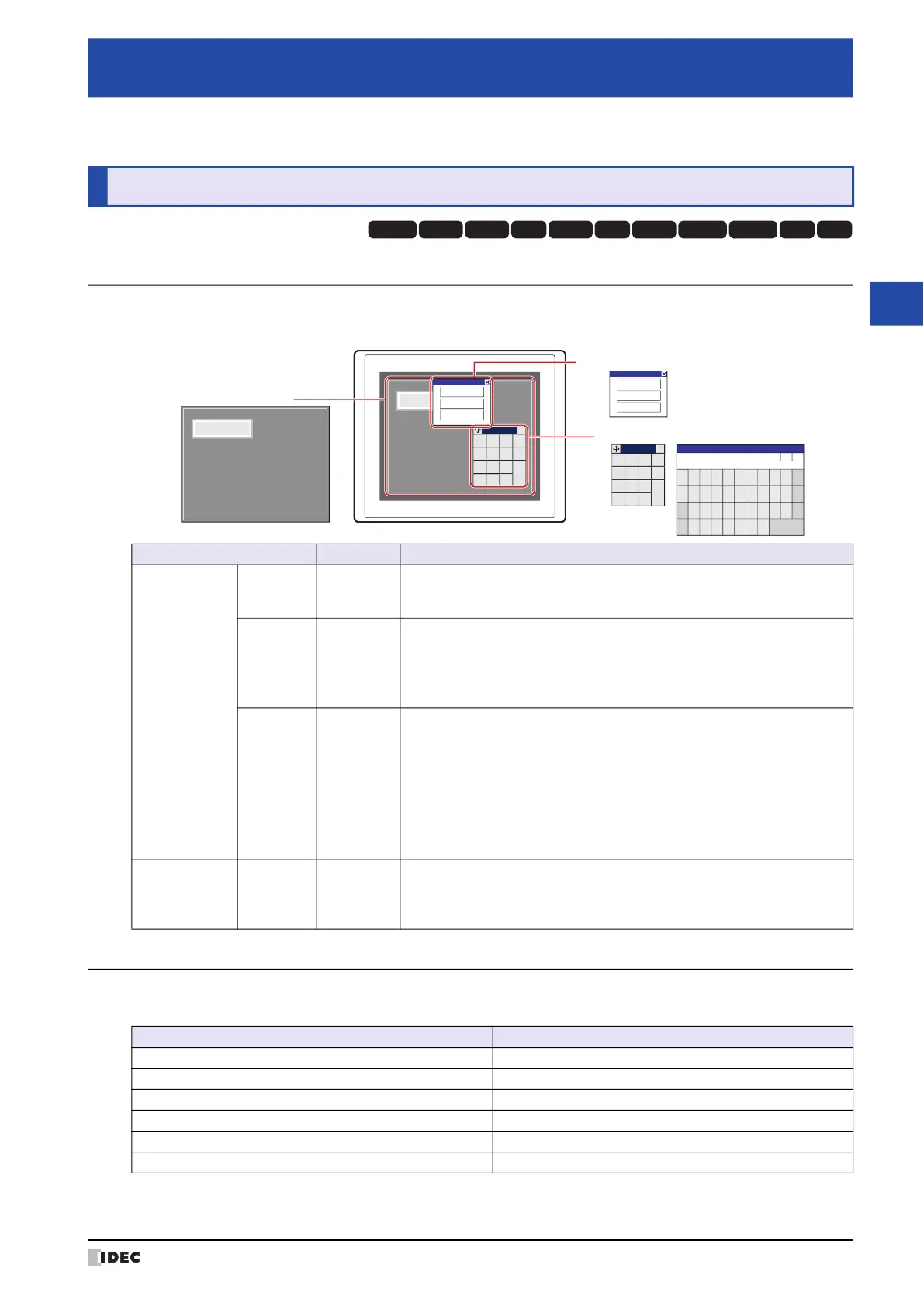
The types of screens offered by the MICRO/I and screens that can be created with the WindO/I-NV4 are given below.
1.2 Screen Size
The screen size differs depending on the MICRO/I model selected. The size of the MICRO/I screen is equal the size of
the Base Screen.
*1 The Keypad that is displayed when operating Numerical and Character Input parts when Standard is selected under Type
in the Keypad menu for Numerical and Character Input parts.
Chapter 5 Screen
1 Screen Overview
HG3G
HG2G-5FHG5G-V HG4G-V HG3G-V HG2G-V HG2G-5T
HG4G HG1G HG1P
HG2J-7U
Screen Type Screen No. Description
Screens that can
be created with
the WindO/I-NV4
Base
Screen
1 to 3000
The screen that is displayed when the MICRO/I is in Run Mode. This screen
places drawing objects and parts on the base and creates a screen that is
displayed on the MICRO/I.
Popup
Screen
1 to 3015
The Popup Screen that is displayed on the Base Screen when the MICRO/I
is in Run Mode. The size and coordinates of the screen can be specified and
this screen can also be moved on the Base Screen.
A Popup Screen for the standard Keypad
*1
will automatically be created in
screen numbers 3001 to 3015.
Password
Input
Screen
3026 to
3033
The Password Input Screen is used to enter the user name and password
required for switching user accounts when the MICRO/I is in Run Mode.
This screen can only be created when the Use Security functions check
box and the Customize Password Input Screens check box in the
Security dialog box are selected. If you are using the Password Input Screen
provided by MICRO/I, you do not need to create the screen. For details, refer
to Chapter 23 “4.1 Entering the Password on the MICRO/I” on page 23-47.
A standard Password Input Screens will automatically be created in screen
numbers 3026 to 3028.
The screen
provided by the
MICRO/I
Maintenance
Screen
–
Using the screen that is displayed when the MICRO/I is in Run Mode, you
can switch from Run Mode to System Mode and load a screen to adjust
device monitor and screen brightness.For details, refer to Chapter 34 “1
Maintenance Screen” on page 34-1.
MICRO/I
1230
1230
0
+
/
−
1
4
7
2
5
8
3
6
9
.
ENT
CLR
CAN
×
0
+
/
−
1
4
7
2
5
8
3
6
9
.
ENT
CLR
CAN
×
Maintenance
System Mode
Device Monitor
Adjust Brightness
Maintenance
System Mode
Device Monitor
Adjust Brightness
Base Screen
Popup Screen Password Input Screen
Maintenance Screen
1
********
User
▲ ▼
2 3 4 5 6 7 8 9 0 BS
Q W E R T Y U I O P CLR
123
abc
A S D F G H J K L CAN
!?# Z X C V B N M ENT
Password
Model Screen Size (W x H)
HG2J-7U 800 x 480 dots
HG5G/4G/3G-V 1024 x 768 dots
HG4G/3G 800 x 600 dots
HG2G-V, HG2G-5F 640 x 480 dots
HG2G-5T 320 x 240 dots
HG1G/1P 480 x 272 dots