5 HG1P
35-78 WindO/I-NV4 User’s Manual
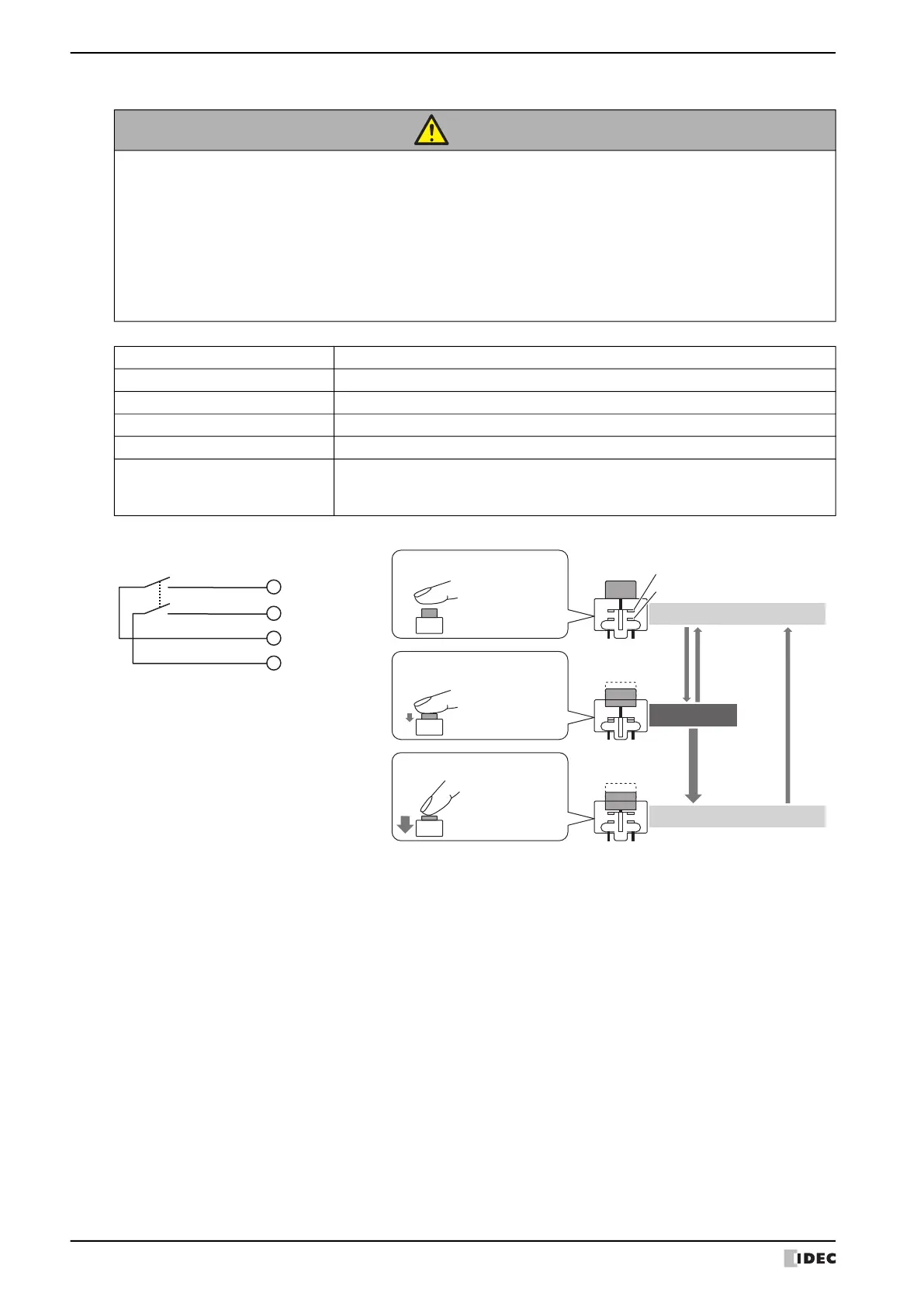
Enabling Switch
CAUTION
• Use the enabling switch through the HG1P optional cable as a control signal for external devices.
• Build the system so that the machine operates only in position 2.
• Use the two contacts of the enabling switch as inputs for a mismatch detection circuit (safety
relay module, etc.).
• The two contacts have been constructed to work independently of each other. For this reason, a
time lag may occur in the operation of the two contacts when the button is pressed to the edge.
When wiring the contacts to two inputs so that they are monitored mutually, design the sequence
control to take into consideration this time difference.
Part Number (Manufacturer) HE6B-M200Y (IDEC)
Number Mounted 1
Contact 2 contacts (external wiring)
Contact Rating 0.7A/DC30V
Monitoring Contact None
Damage Limits
Mechanical: Position 1→2→1: 1,000,000 operations minimum
Position 1→2→3→1: 100,000 operations minimum
Electrical: 100,000 operations minimum
3 Positions
(OFF-ON-OFF)
B1
B2
14 (B_NO1)
5 (B_NO2)
3 (B_C1)
4 (B_C2)
Removable Connector
Pin Number (Name)
Position 1
3 Positions Enabling Switch
When the button
is not pressed
Push Lightly Release
Movable Contact
Contact Terminal
Push Further
Release
Position 2
When the button
is lightly pressed
Position 3
When the button
is firmly pressed
OFF
ON
OFF

 Loading...