Peripheral devices
20
INSTALLATION AND WIRING
2.1.2 Peripheral devices
Check the model of the inverter you purchased. Appropriate peripheral devices must be selected according to the capacity.
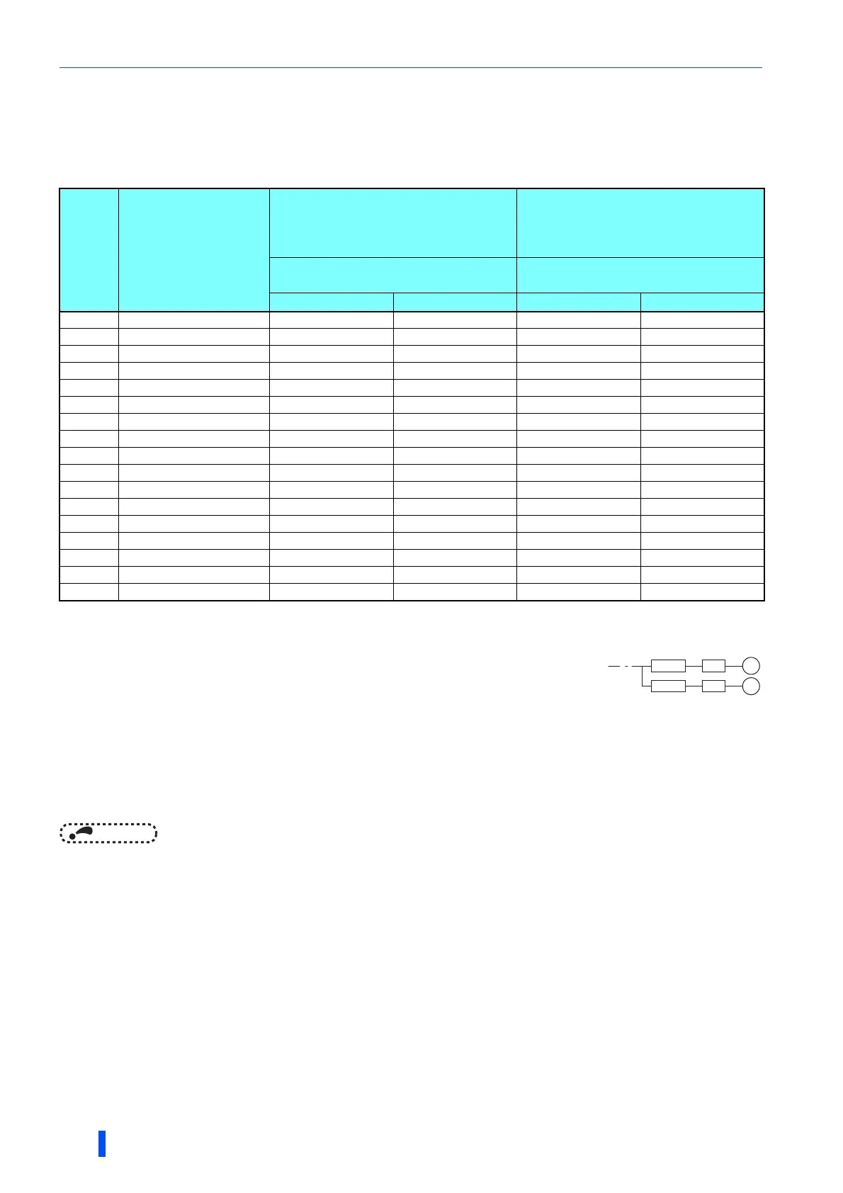
Refer to the table below to prepare appropriate peripheral devices.
• 200 V class
NOTE
• When the inverter capacity is larger than the motor capacity, select an MCCB and a magnetic contactor according to the
inverter model, and select cables and reactors according to the motor output.
• When the breaker on the inverter's input side trips, check for the wiring fault (short circuit), damage to internal parts of the
inverter etc. The cause of the trip must be identified and removed before turning ON the power of the breaker.
Motor
output
(kW)
Applicable inverter
model
Molded case circuit breaker (MCCB)
or
earth leakage circuit breaker (ELB) (NF,
NV type)
Input-side magnetic contactor
Power factor improving (AC or DC)
reactor
Power factor improving (AC or DC)
reactor
Without With Without With
0.4 FR-A820-00046(0.4K) 5A 5A S-T10 S-T10
0.75 FR-A820-00077(0.75K) 10A 10A S-T10 S-T10
1.5 FR-A820-00105(1.5K) 15A 15A S-T10 S-T10
2.2 FR-A820-00167(2.2K) 20A 15A S-T10 S-T10
3.7 FR-A820-00250(3.7K) 30A 30A S-T21 S-T10
5.5 FR-A820-00340(5.5K) 50A 40A S-N25 S-T21
7.5 FR-A820-00490(7.5K) 60A 50A S-N25 S-N25
11 FR-A820-00630(11K) 75A 75A S-N35 S-N35
15 FR-A820-00770(15K) 125A 100A S-N50 S-N50
18.5 FR-A820-00930(18.5K) 150A 125A S-N65 S-N50
22 FR-A820-01250(22K) 175A 150A S-N80 S-N65
30 FR-A820-01540(30K) 225A 175A S-N95 S-N80
37 FR-A820-01870(37K) 250A 225A S-N150 S-N125
45 FR-A820-02330(45K) 300A 300A S-N180 S-N150
55 FR-A820-03160(55K) 400A 350A S-N220 S-N180
75 FR-A820-03800(75K) 400A S-N300
90 FR-A820-04750(90K) 400A S-N300
Assumes the use of an IPM motor MM-CF or a Mitsubishi 4-pole standard motor with the power supply
voltage of 200 VAC 50 Hz.
Select an MCCB according to the power supply capacity.
Install one MCCB per inverter.
For the use in the United States or Canada, provide the appropriate UL and cUL listed fuse or UL489
molded case circuit breaker (MCCB) that is suitable for branch circuit protection. (Refer to the
Instruction Manual (Startup).)
The magnetic contactor is selected based on the AC-1 class. The electrical durability of magnetic contactor is 500,000 times. When the
magnetic
contactor is used for emergency stops during motor driving, the electrical durability is 25 times.
If using an MC for emergency stop during motor driving, select an MC regarding the inverter input side current as JEM1038-AC-3 class rated
current. When using an MC on the inverter output side for commercial-power supply operation switching using a general-purpose motor,
select an MC regarding the rated motor current as JEM1038-AC-3 class rated current.
MCCB INV
MCCB INV
M
M

 Loading...


