(N) Operation via communication and its settings
PARAMETERS
575
5
GROUP
N
Refer to page 566 for data formats (A, A1, A2, B, C, C1, D, E, E1, E2, E3, F)
Turning OFF the power supply while clearing parameters with H5A5A or H55AA returns the communication parameter settings to the initial
settings.
Refer to the calibration parameter list below for details on calibration parameters.
The gain frequency can be also written using Pr.125 (instruction code: H99) or Pr.126 (instruction code: H9A).
Set frequency
(RAM)
Write
HED
Write the set frequency/speed into the RAM or EEPROM.
H0000 to HE678 (0 to 590.00Hz): frequency in 0.01Hz increments
(The display can be changed to the rotations per minute using Pr.37,
Pr.144 and Pr.811. (Refer to page 357))
• To change the set frequency consecutively, write data to the inverter
RAM. (Instruction code: HED)
4 digits
(A,C/D)
Set frequency
(RAM, EEPROM)
HEE
Inverter reset Write HFD
H9696: Inverter reset
• As the inverter is reset at the start of communication by the computer, the
inverter cannot send reply data back to the computer.
4 digits
(A,C/D)
H9966: Inverter reset
• When data is sent normally, ACK is returned to the computer, and then
the inverter is reset.
4 digits
(A,D)
Faults history
batch clear
Write HF4 H9696: Faults history batch clear
4 digits
(A,C/D)
Parameter clear
All clear
Write HFC
All parameters return to initial values.
Whether to clear communication parameters or not can be selected
according to the data.
• Parameter clear
H9696: Communication parameters are cleared.
H5A5A: Communication parameters are not cleared.
• All parameter clear
H9966: Communication parameters are cleared.
H55AA: Communication parameters are not cleared.
For the details of whether or not to clear parameters, refer to page 711.
When a clear is performed with H9696 or H9966, communication related
parameter settings also return to the initial values. When resuming the
operation, set the parameters again.
Performing a clear will clear the instruction code HEC, HF3, and HFF
settings.
Only H9966 and H55AA (all parameter clear) are valid during the password
lock (refer to page 269).
4 digits
(A,C/D)
Parameter
Read H00 to H63
Refer to the instruction code (page 711) and write and/or read parameter
values as required.
When setting Pr.100 and later, the link parameter extended setting must be
set.
4 digits
(B.E/D)
Write H80 to HE3
4 digits
(A,C/D)
Link parameter
Extended setting
Read H7F
Parameter settings are switched according to the H00 to H0D settings.
For details of the settings, refer to the instruction code (page 711).
2 digits
(B.E1/D)
Write HFF
2 digits
(A1,C/D)
Second parameter
changing
(instruction code
HFF = 1, 9)
Read H6C
When setting the calibration parameters
H00: Frequency
H01: Parameter-set analog value
H02: Analog value input from terminal
2 digits
(B.E1/D)
Write HEC
2 digits
(A1,C/D)
Multi command
Write/
Read
HF0
Available for writing 2 commands, and monitoring 2 items for reading data
(refer to page 578 for detail)
10 digits
(A2,C1/D)
Inverter model monitor
Inverter
model
Read H7C
Reading inverter model in ASCII code.
"H20" (blank code) is set for blank area
Example of "FR-A840-1 (FM type)"
H46, H52, H2D, H41, H38, H34, H30, H2D, H31, H20, H20 ......... H20
20 digits
(B,E3/D)
Capacity Read H7D
Reading inverter ND rated capacity in ASCII code.
Data is read in increments of 0.1kW, and rounds down to 0.01kW
increments
"H20" (blank code) is set for blank area
Example
0.75K......... "7" (H20, H20, H20, H20, H20, H37)
6 digits
(B,E2/D)
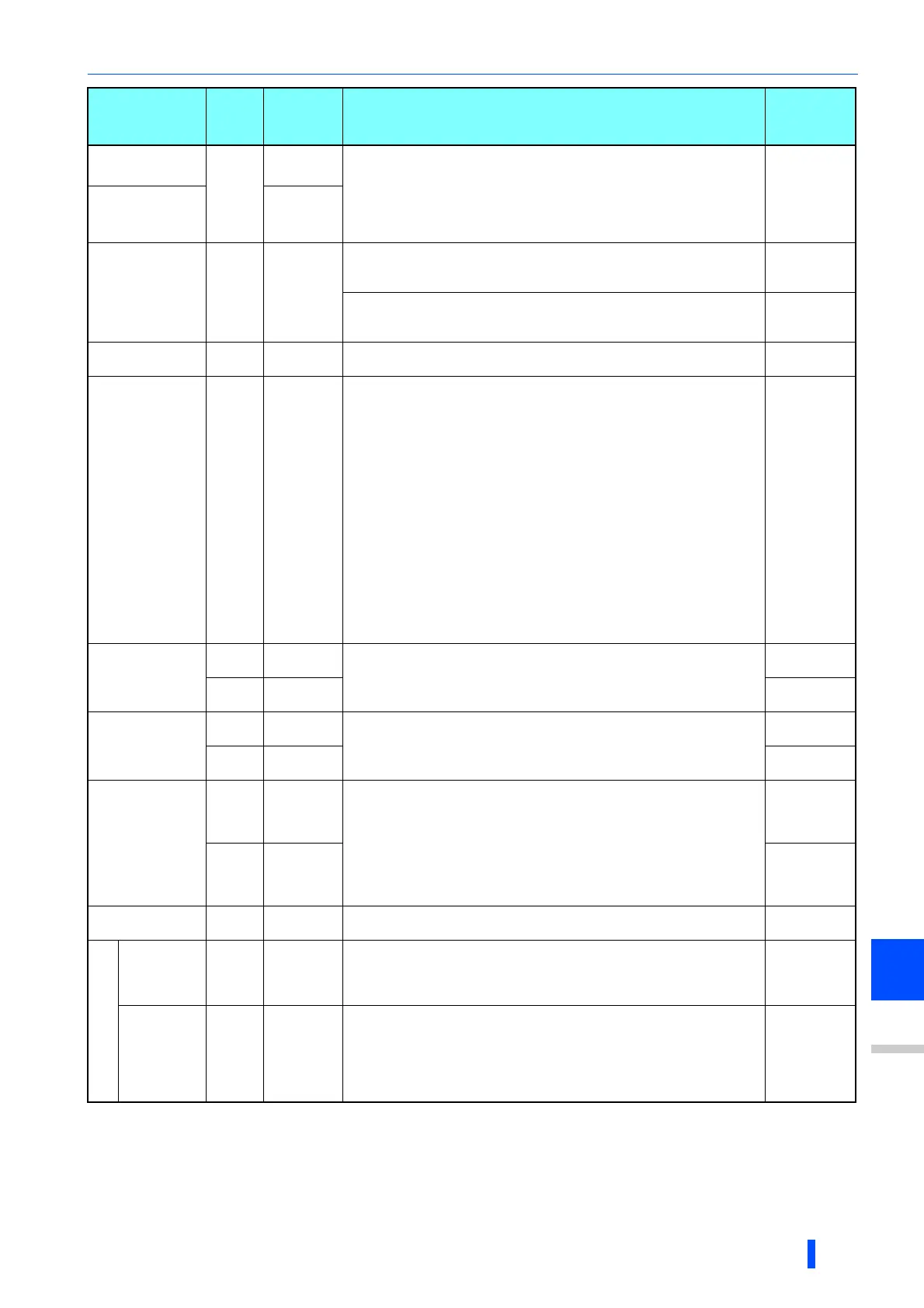
Item
Read/
Write
Instruction
code
Data description
Number of
data digits
(Format)

 Loading...


