9 Field-IQ system setup Equipment calibration for Field-IQ
4.
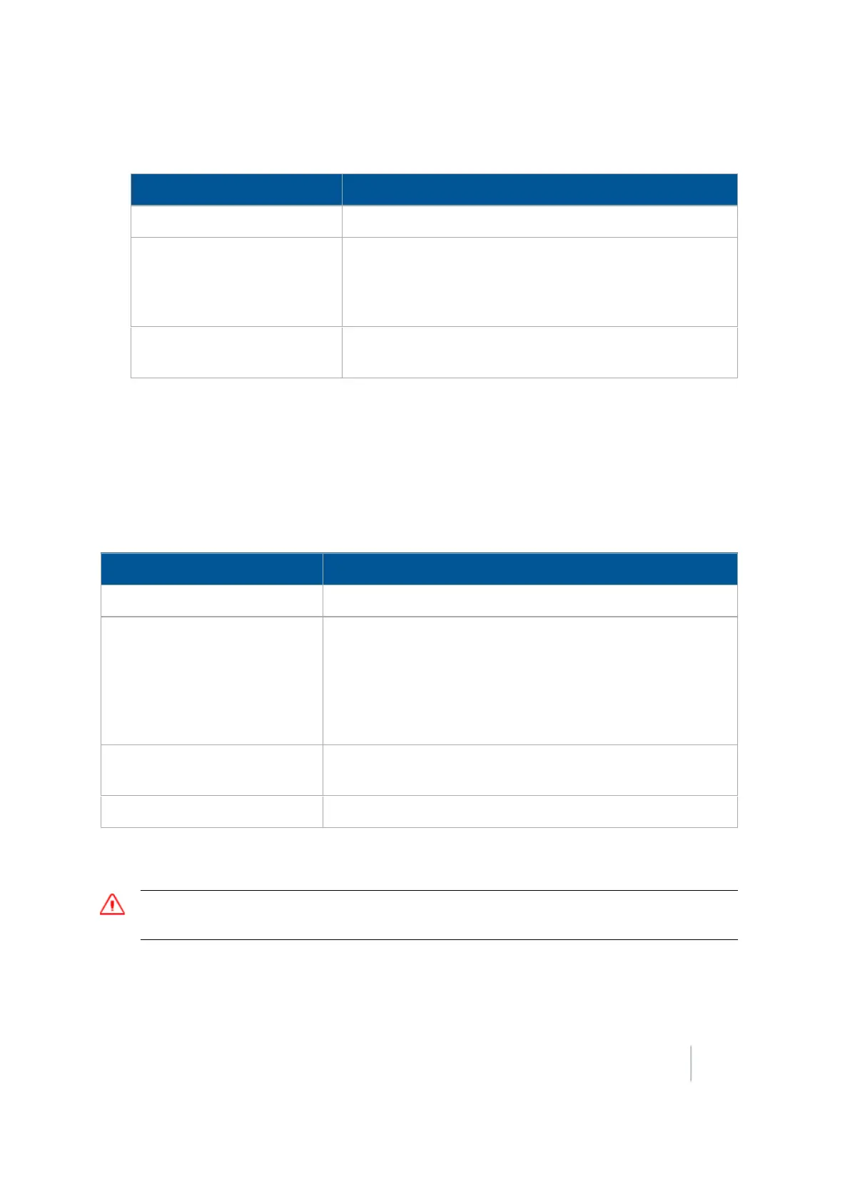
Tap Start. The next screen provides the status of each motor.
Status Explanation
No Error The test was successful.
Motor Stalled The motors did not have sufficient oil flow; ensure the
correct orifice size is installed for each motor. For more
information, refer to the Rawson System Installation
Instructions.
Disconnected The Rawson Control Module cannot communicate with the
motor.
5. Tap Stop to return to the Field-IQ Calibration screen.
PWM valves calibration
Drive calibration
From the Field-IQ Calibration screen, select Drive Calibration under the valve you want to calibrate.
Enter the appropriate settings on each tab.
Tab Explanation
Drive Limits Enter the minimum and maximum flow values.
Auto-Tuning
Moving parts during this operation. Ensure that the
implement is safe to operate.
Follow the on-screen instructions to auto-tune the system.
Do not perform the auto-tuning function if you have loaded a
preset configuration file. Use the predefined configuration
settings appropriate for your vehicle.
Drive Settings Turn the master switch on and vary the rates. Adjust values if
needed.
Info Shows the results and drive limits of your calibration.
Flow calibration
WARNING – During flow calibration, the machine will become operational. Take all necessary precautions to
ensure user safety. Failure to do so may result in serious injury or death.
The Field-IQ system Calibration option only displays on the Configuration screen if you have at least
one Field-IQ system Rate and Section control module installed.
Version 9.25, Revision B FM-1000 Integrated Display User Guide 239