3 Analog I/O Modules
30-18 WindO/I-NV4 User’s Manual
■ Filter
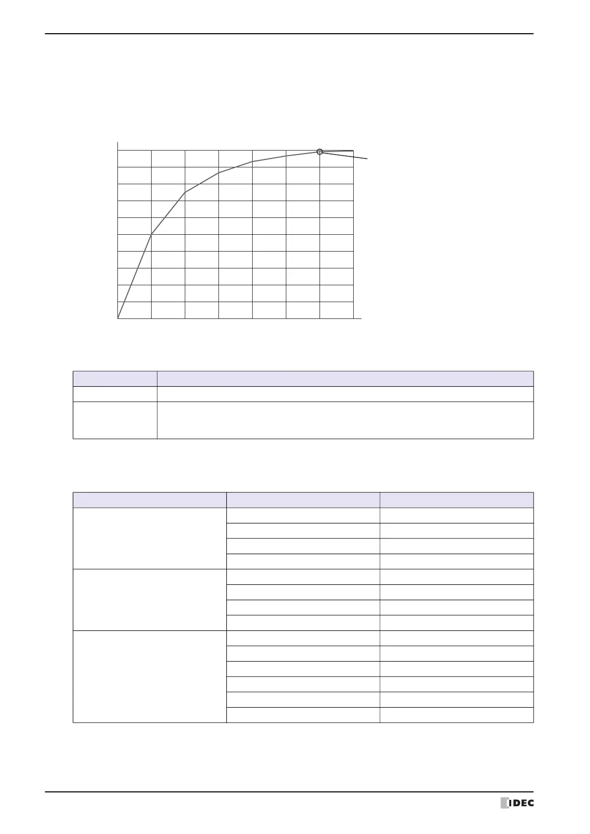
The analog input is filtered so it reaches approximately 99% of the analog input in the set time. Rapid fluctuations in
the analog input can be reduced by setting the filter, but increasing the filter slows down the tracking of fluctuations
in the analog input. The filter must be set for each channel.
Input filter example
■ Sampling Time
Analog values are converted to digital values at the interval of the sampling time. Depending on the analog I/O
module, you may be able to change the sampling time setting.
Filter Description
0 msec The value is not filtered.
50 to 50,000 msec
The analog input filter can be set in 50 milliseconds increments.
The analog input is filtered so that approximately 99% of the analog input is reached in the
specified filter.
-20
0
Elapsed time (msec)
Analog input data after filtering (%)
10
20
30
40
50
60
70
80
90
100
0 20 40 60 80 100 120
Reaches approximately 99% of the analog
input in the set filter (100 msec).
Type Signal Type Sample Time
FC6A-J2C1
FC6A-J2C4
0 to 10V DC 1 msec
-10 to +10V DC 1 msec
0 to 20mA DC 1 msec
4 to 20mA DC 1 msec
FC6A-J4A1
FC6A-J4A4
0 to 10V DC 1 msec or 10 msec
-10 to +10V DC 1 msec or 10 msec
0 to 20mA DC 1 msec or 10 msec
4 to 20mA DC 1 msec or 10 msec
FC6A-J8A1
FC6A-J8A4
0 to 10V DC 1 msec or 10 msec
-10 to +10V DC 1 msec or 10 msec
0 to 20mA DC 1 msec or 10 msec
4 to 20mA DC 1 msec or 10 msec
Expansion 0 to 20mA DC 1 msec or 10 msec
Expansion 4 to 20mA DC 1 msec or 10 msec

 Loading...