1 Bit Devices
33-2 WindO/I-NV4 User’s Manual
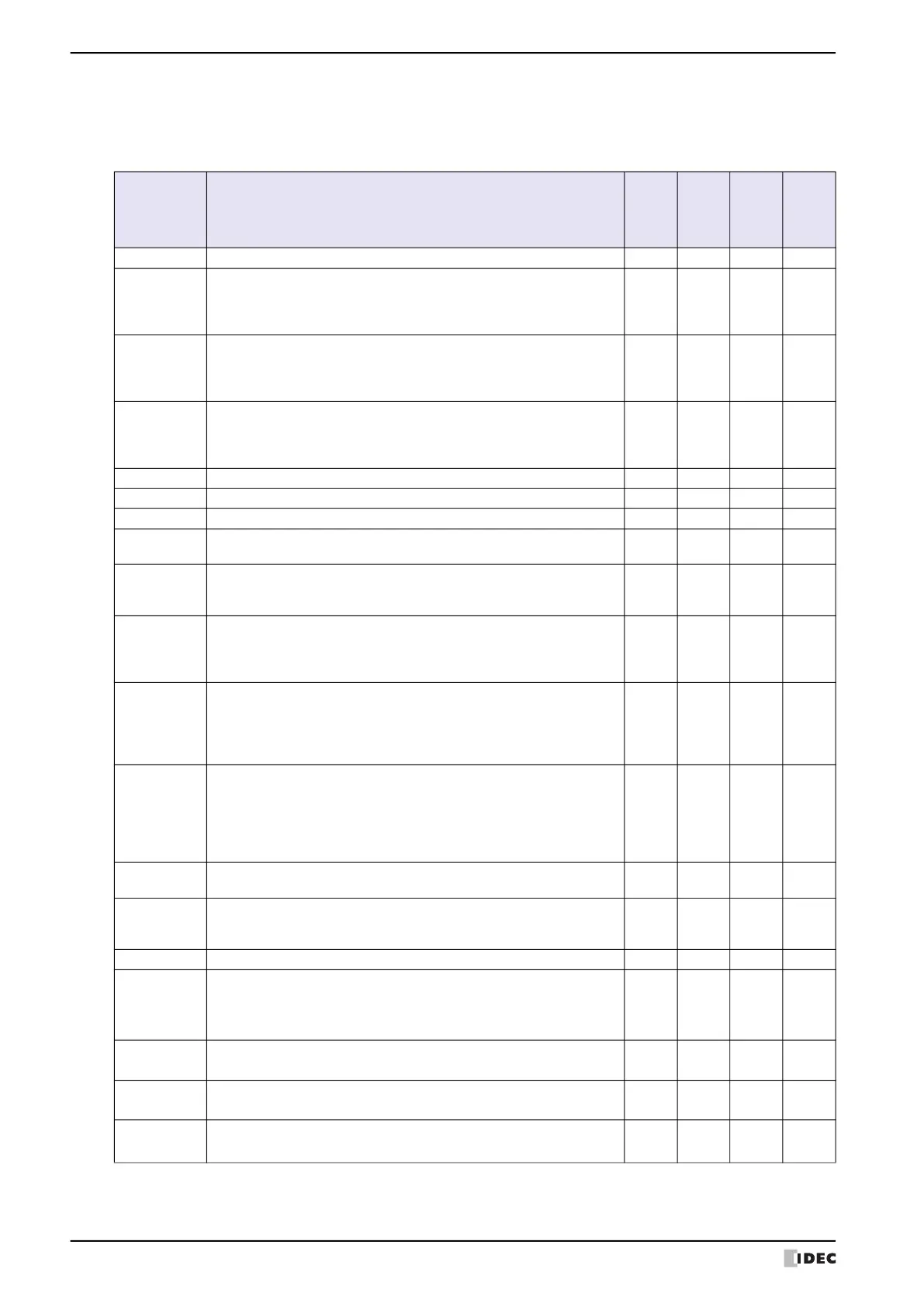
■ HMI Special Relay (LSM)
A specific function is assigned for each of the 96 special internal relay (LSM0 to LSM95). The supported device
addresses vary based on the model.
Yes: Supported, No: Not supported, (blank): Reserved
*6 USB flash drive inserted in USB2 for HG2J-7U
*7 USB flash drive inserted in USB1 for HG2J-7U, SD memory card for HG5G/4G/3G/2G-V, HG4G/3G and HG2G-5F
Device
Address
Function/Part
HG2J
-7U
HG5G/
4G/3G/
2G-V
HG4G/
3G,
HG2G-
5F
HG2G
-5T,
HG1G
/1P
LSM0 Always set to 1. Yes Yes Yes Yes
LSM1
When the default screen is displayed after the power turned ON or when
the Base Screen swicthed, the value of this bit is 1 only on the second scan.
It also operates when switching text group or user account, or
resetting the display screen.
Yes Yes Yes Yes
LSM2
When the default screen is displayed after the power turned ON or when
the Base Screen swicthed, the value of this bit is 1 only on the first scan.
It also operates when switching text group or user account, or
resetting the display screen.
Yes Yes Yes Yes
LSM3
When the default screen is displayed after the power turned ON or when
the Base Screen swicthed, the value of this bit is 0 only on the first scan.
It also operates when switching text group or user account, or
resetting the display screen.
Yes Yes Yes Yes
LSM4 Alternates between 0 and 1 with each scan. Yes Yes Yes Yes
LSM5
When Popup Screen is opened, the value of this bit is 1 only on the first scan.
Yes Yes Yes Yes
LSM6 While touch panel is pressed, the value of this bit is 1. Yes Yes Yes Yes
LSM7
Alternates between 0 and 1 each time data is read (read scan) from all the
external device addresses being used by External Device Communication 1.
Yes Yes Yes Yes
LSM8
When the power is turned ON, the value of this bit changes to 1.
When switching to another screen from the default screen or when
switching text group or user account, then the value changes to 0.
Yes Yes Yes Yes
LSM9
When value changes from 0 to 1, the backup data stored in flash
memory is restored.
When it becomes 1 value does not become 0 until the Touch is reset
or 0 is written.
Yes Yes Yes Yes
LSM10
When switched from 0 to 1, the current backlight setting and the data
for Keep Relays and Keep Register configured in the Data Storage
Area are transferred to the flash memory.
Once LSM10 switches to 1, it does not change to 0 until MICRO/I
recycles power or 0 is written to LSM10.
Yes Yes Yes Yes
LSM11
When the default screen gets displayed after the power turned ON or
when the Base Screen gets switched, the values of all external device
addresses in use are read first. Then the bit changes from 0 to 1. The
bit remains 1 until the screen gets switched to another screen.
It also operates when switching text group or user account, or
resetting the display screen.
Yes Yes Yes Yes
LSM12
When Popup Screen is closed, the value of this bit is 1 only on the
first scan.
Yes Yes Yes Yes
LSM13
Value becomes 0 when Popup Screen is opened, and then changes
from 0 to 1 after the values of all external device addresses being
used by that Popup Screen are read.
Yes Yes Yes Yes
LSM14 to 17 Reserved
LSM18
When value changes from 0 to 1, access to USB flash drive
*6
is
stopped. The access state can be checked with the value of LSM19.
When it becomes 1 value does not become 0 until the MICRO/I is
reset or 0 is written.
Yes Yes Yes Yes
LSM19
Bit is 1 during USB flash
*6
access. When 0, the USB flash
*6
can be
removed.
Yes Yes Yes Yes
LSM20
Access to the external memory device
*7
stops when this bit is switched
from 0 to 1. The access state can be checked with the value of LSM21.
Yes Yes Yes No
LSM21
Bit is 1 during external memory device
*7
access. When 0, the external
memory device
*7
can be removed.
Yes Yes Yes No
 Loading...