5 HG1P
35-84 WindO/I-NV4 User’s Manual
5.8 Wiring
● HG1P Optional Cable (HG9Z-XCP13/-XCP15/-XCP17)
This cable connects the HG1P and external devices.
■ Specifications
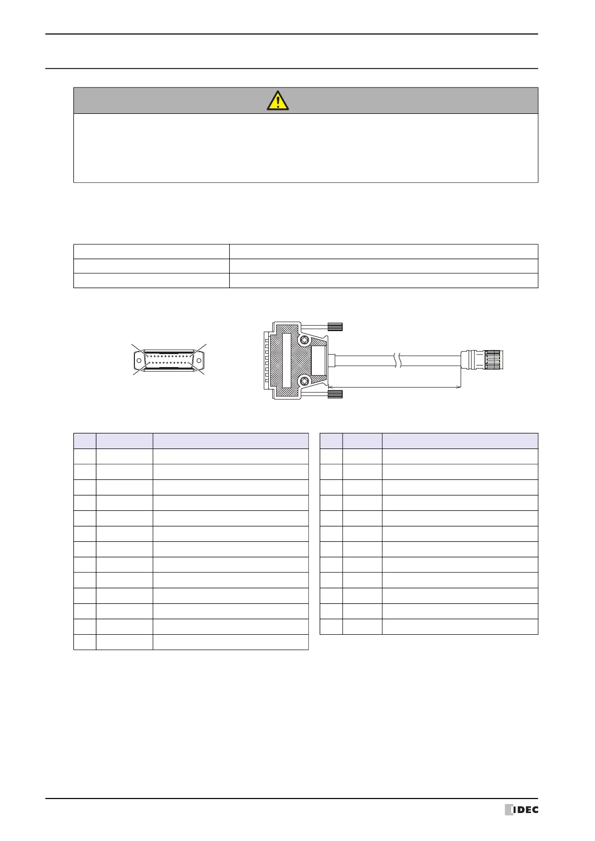
■ Outline Drawing
■ Connector Wiring Table
CAUTION
• Turn off the power supply before wiring.
• Make the wiring as short as possible and run all wires as far away as possible from high-voltage
and large-current cables. Follow all the procedures and precautions when wiring the HG1P.
• Separate the HG1P power supply wiring from the power lines of I/O devices and motor
equipment.
• Connect the functional ground terminal to make sure of correct operation.
Communication Interface Serial Interface (RS422/485) or Ethernet Interface
Connector for the External Devices D-sub 25-pin Male Connector (Jackscrew M2.6)
Length 3m, 5m, 7m
Cable Length 3m, 5m, 7m
113
2514
Connector for the External Devices
(View of mating surface of the removable connector)
No. Name Function No. Name Function
1 FG Frame Ground 14 NC -
2 RDB-/TP1- Receive Data (-) 15 NC -
3 RDA+/TP1+ Receive Data (+) 16 NC -
4 SDB-/TP0- Send Data (-) 17 NC -
5 SDA+/TP0+ Send Data (+) 18 C_NC1 Selector Switch Contact 1 (NC)
6 SG Communication Signal Ground 19 C_NO1 Selector Switch Contact 1 (NO)
7 NC - 20 C_C1 Selector Switch Contact 1 (COM)
8 NC - 21 B_NO2 Enabling Switch Contact 2 (NO)
9 B_NO1 Enabling Switch Contact 1 (NO) 22 B_C2 Enabling Switch Contact 2 (COM)
10 B_C1 Enabling Switch Contact 1 (COM) 23 A_NC21 Emergency Stop Switch Contact 2 (NC)
11 A_NC11 Emergency Stop Switch Contact 1 (NC) 24 A_NC22 Emergency Stop Switch Contact 2 (NC)
12 A_NC12 Emergency Stop Switch Contact 1 (NC) 25 DC24V+ HG1P 24V DC Power Supply (+)
13 DC24V- HG1P 24V DC Power Supply (-)
 Loading...