Function Reference 165
imc CANSAS Users Manual - Doc. Version 1.9 - 05.12.2014© 2014 imc Meßsysteme GmbH
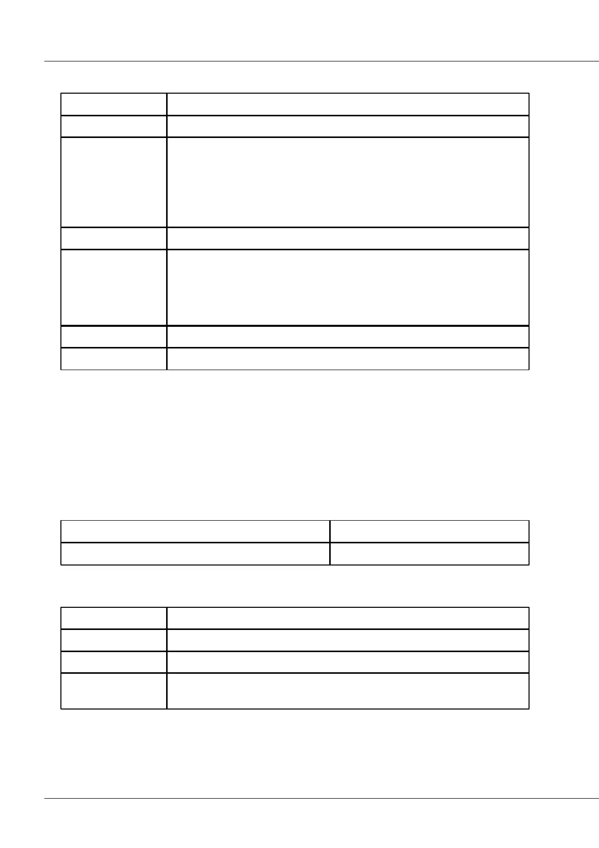
4.10.41 Low-pass filter
Filter characteristic
Butterworth
Bessel
Chebychev, ripple: 0.5 dB
Chebychev, ripple: 1.0 dB
Chebychev, ripple: 3.0 dB
Description: Filtering of the input channels with a low-pass filter. The filter coefficients are calculated
from the parameters supplied by the user.
Notes: A condition for effective filtering is that the cut-off frequencies are significantly below half of the
input channel's sampling rate. The closer the cut-off frequencies are to the input channel's sampling rate,
the more imprecise the filter's amplitude response.
The cut-off frequency's input range depends on the input channel's sampling rate, the filter's order and
on the filter characteristic.
The result clock pulse may not exceed the input channel's sampling rate.
Data types:
4.10.42 Maximum
Channel whose maxima within each reduction interval are to be determined
Data rate of result channel
Channel with the maxima of the input channel within the data reduction
interval.
Description: The maximum values within each reduction interval in the channel are determined. The
reduction interval is the clock pulse of the result channel. The values returned are a sequence of the
maxima found.