SCI8, SCI16 505
imc CANSAS Users Manual - Doc. Version 1.9 - 05.12.2014© 2014 imc Meßsysteme GmbH
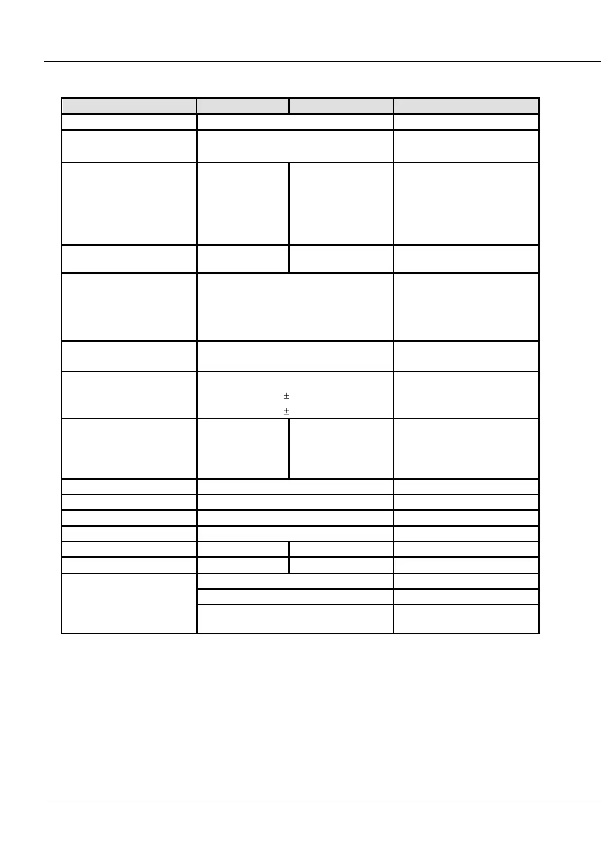
7.20 SENT
SAE J2716 (2007, 2008, 2010)
8
respectively for pins V
Supply
, SIG and GND
Isolated individually from each
other and from CHASSIS
Input supply voltage
of the SENT sensor
at 20°C
individually for each sensor
no general short-circuit
protection. However, one supply
may be short-circuited for a short
time.
Supply current
of the SENT sensor
defined in accordance with ISO 11898
up to 1 Mbit/s
terminal connection isolated to
power supply / CHASSIS of the
CANSAS module;
as per CiA® Draft Standard 102
Version 2.0
Isolation
CAN bus
SENT-inputs
to system ground
nominal; tested 300 V (10 s)
nominal; tested 300 V (10 s)
-0.3 V to 0.3 V + V
Supply
SIG connection to ground
of the input
with short interference pulses
long-term
PHOENIX (MC 1,5/4STF-3,81)
CAN (IN / OUT),
power supply (alternatively)