IGN 483
imc CANSAS Users Manual - Doc. Version 1.9 - 05.12.2014© 2014 imc Meßsysteme GmbH
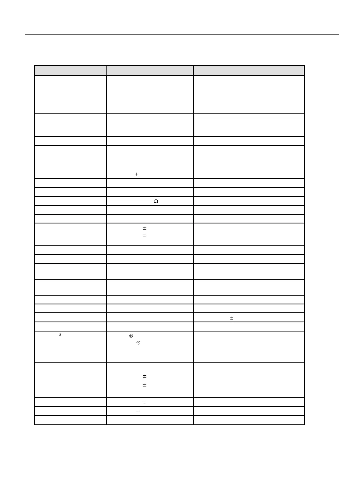
7.12 INC4
Datasheet Version 1.4 (4 incremental counter inputs)
4 channels with 2 tracks (X, Y) each
1 index channel
all fully conditioned
inputs isolated from CAN-Bus and supply, but
not mutually.
displacement, angle, events,
time, frequency;
velocity, RPMs
Sampling rate (CAN output)
Time resolution of
measurement
frequency stability
deterioration
33 ns
<100 ppm
< 5 ppm / year
counter frequency 32 MHz
(primary sampling rate)
globally selectable in 0.1 V steps
globally selectable in 0.1 V steps
Input voltage range
(differential)
linear range
maximum, outside of linear range: max. non-
linearity uncertainty: 300 ns
Common mode input voltage
bypass (without filter),
20 kHz, 2 kHz, 200 Hz
adjustable (globally for all channels)
Butterworth, 2nd order
70 dB (typ.), 50 dB (min.)
60 dB (typ.), 50 dB (min.)
deterioration < 5 ppm / year
"CiA DS 301 V4.0.2" and
"CiA DS 404V1.2"
supports 4 PDOs in
INT16, INT32, and FLOAT
isolation:
CAN-Bus
power supply input
analog input
to CHASSIS
nominal; testing: 300 V (10 s)
nominal; testing: 300 V (10 s)
analog reference ground: CHASSIS