UNI8: universal 417
imc CANSAS Users Manual - Doc. Version 1.9 - 05.12.2014© 2014 imc Meßsysteme GmbH
For an (optional) sensor supply with ±15 V ground referenced current measurement is not possible.
The pin I;¼Bridge is used as –15 V pin.
For the former UNI8 equipped with a 350 quarter bridge completion, ground referenced current
measurement is not possible!
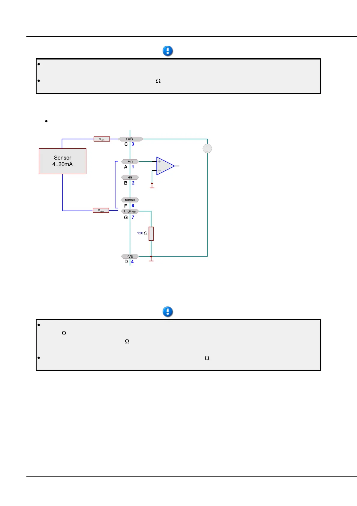
6.20.3.3 2-wire for sensors with a current signal and variable supply
E.g. for pressure transducers 4 mA to 20 mA.
Transducers which translate the
physical measurement quantity into
their own current consumption and
which allow variable supply voltages
can be configured in a two-wire circuit.
In this case, the device has its own
power supply and measures the
current signal.
In the settings dialog on the index card
Universal amplifiers / General, a supply
voltage is set for the sensors, usually
24 V. The channels must be configured
for Current measurement.
The sensor is supplied with power via Terminals +VB(C) and +I; ¼Bridge(G)
The signal is measured by the unit between +IN(A) and -VB(D). For this reason, a wire jumper must be
positioned between Pins +IN(A) and +I; ¼Bridge(G) inside the connector pod.
There is a voltage drop across the resistances of the leadwires and the internal measuring resistance
of 120 which is proportional to the amperage. This lost voltage is no longer available for the supply
of the transducer (2.4 V = 120 * 20 mA). For this reason, you must ensure that the resulting supply
voltage is sufficient. It may be necessary to select a leadwire with a large enough cross-section.
For the former UNI8: If the amplifier is equipped with a 350 quarter bridge completion, ground
referenced current measurement is not possible! Thus this operation is not possible, too.