526 Pin configuration and power supply
imc CANSAS Users Manual - Doc. Version 1.9 - 05.12.2014© 2014 imc Meßsysteme GmbH
8.1.1.3 Specification of components used
In imc CANSAS, the following components are used for the CAN-connection. Use this as a reference for
the purpose of especially critical applications, e.g. in connection with bit-timing.
CAN-Controller:
Oscillator Type:
CAN transceiver:
Slope resistor:
DSP TMS320LF2407A (Texas Instruments)
SG8002JFPCM-10M Hz (Epson, crystal oscillator, 10M Hz, -40 +85°C,±100ppm);
PCA82C250 (Philips)
1k
8.1.2 SL modules CAN-Bus connectors
Below is shown the pin configuration of the CAN-bus plug/socket set (CAN IN and CAN OUT) at the imc
CANSAS modules with SL housing. Only differences to the standard imc CANSAS modules are described
here.
A general description of the CAN-bus can be found in Chapter "Startup" of this documentation.
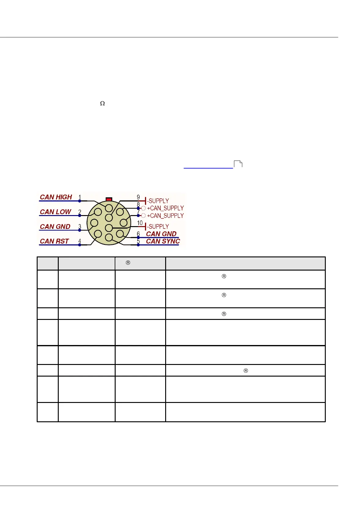
8.1.2.1 CAN-Bus pin configuration and contact wiring
connected as per CiA . CAN-Bus reference ground.
imc CANSAS-specific: imc CANSAS Reset ( for startup with
Reset Connector). The Reset plug has a shortcut to PIN 3
(GND).
imc CANSAS-specific: Additional line for a sync signal (1 Hz).
Generally 5 V to CAN Ground.
connected to Pin 3, as per CiA
imc CANSAS-specific: + imc CANSAS voltage supply +10 V..
+50V. The module can be supplied via this connector
(and Pin 9 + 10).
imc CANSAS-specific: - imc CANSAS voltage supply (Negative
pole of supply respectively. 0V).
Both 10-pin sockets are directly connected. In that way all circuit points can be connected through to the
next imc CANSAS module.
37