µ-CANSAS-V1 437
imc CANSAS Users Manual - Doc. Version 1.9 - 05.12.2014© 2014 imc Meßsysteme GmbH
6.21.2.3 Voltage balancing via measurement window
In the measurement window, the balancing is performed by selecting the channel and touching the
Balance button. Alternatively, the Channel menu offers the command Perform balancing for selections.
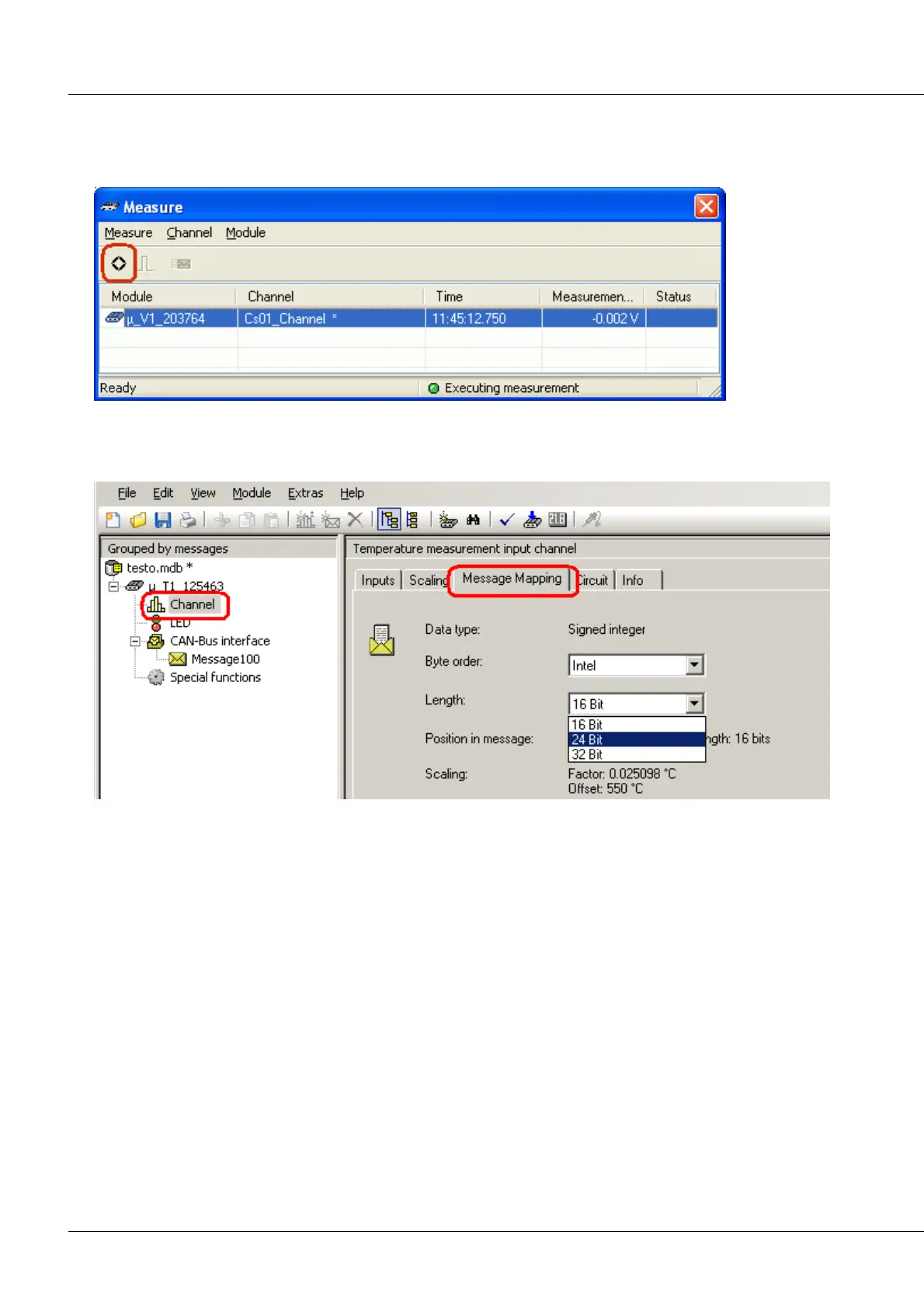
µ-CANSAS-U1: voltage balancing via measurement window
6.21.3 Message Mapping
The modules belonging to the imc µ-CANSAS group work with a maximal resolution of 24 bits. The
Message Mapping page also offers a message length of 32 bits, in which case a value in 32-bit Float
format is transferred.
If four single-channel imc µ-CANSAS modules are connected via a imc µ-CANSAS-HUB4, note the
following: if the values from four imc µ-CANSAS modules are to fit into one message, then a channel’s
length is limited to 16 bits. Since a message can transport a maximum of 8 data bytes, this amounts to
only 2 bytes per channel. If 24 bits per channel are to be used, then with HUB at least two messages must
be created for four channels
6.21.4 External Supply voltage +5 V/+10 V (isolated)
At the imc µ-CANSAS-V1’s connection terminals, a supply voltage which is software-adjustable to either
+5 V or +10 V is available for external sensors. This source is insulated and is connected via the contacts
+SUPPLY and -SUPPLY.
Internally, this +5 V/+10 V supply output is electronically protected from short-circuiting and can carry a
maximum load of 210 mW.