374 Properties of the Modules
imc CANSAS Users Manual - Doc. Version 1.9 - 05.12.2014© 2014 imc Meßsysteme GmbH
6.18.3 Temperature measurement
The input channels are designed for measurement with thermocouples and Pt100-sensors (RTD,
platinum resistance thermometers as per DIN and IEC 751). Any combinations of the two sensor types
can be connected.
6.18.3.1 Thermocouple measurement
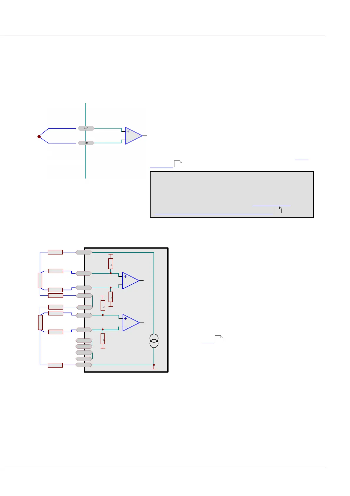
The common thermocouple types make use of linearization
by characteristic curve. All common thermocouple types with
their characteristic curves are supported. A combination of
thermocouple measurement and Pt100 measurement is
possible.
The cold-junction compensation necessary for thermocouple
measurements is built into the imc thermo-connector (ACC/
DSUB-T4 ).
Effective suppression of 50 Hz or 60 Hz signal components
can only be guaranteed for sampling rates of 1s or slower
(SCI8 from 0,5s).
For further information see Chapter: Measurement
technique – sampling rates, scanner-concept .
6.18.3.2 PT100 (RTD) - Measurement
-IN1
+I1
10
M
+IN1
10
M
R
cable
RTD
(PT100)
R
cable
R
cable
R
cable
+
-
-I4
410µA
-I3
+I4
+I3
-I2
-IN2
10
M
+IN2
10
M
RTD
(PT100)
R
cable
R
cable
-I1
R
cable
R
cable
+I2
Along with Along with thermocouples, Pt100 sensors
can also be connected, in 4-wire configuration. An
extra reference current source feeds an entire chain
of up to four serially connected sensors.
The imc thermoplug has 4 contacts which are
available for the purpose of 4-wire measurements.
These current-supply contacts are internally wired so
that the reference current loop is automatically
closed when all four Pt100 units are connected. This
means that the–I contact of one channel is
connected to the +I contact of the next channel (see
the sketch here ). Therefore, for channels not
connected to a P100 sensor, a wire jumper must be
used to connect the respective "+Ix" and "-Ix"
contacts.
Normal DSUB-15 connectors don't come with these extra "auxiliary contacts" for 4-wire connections. This
means that you must take steps to ensure that the reference current flows through all Pt100 units. Only
"+I1" (DSUB(9), Terminal K1, "(RES.)") and "–I4" (DSUB(6), Terminal K10, "(GND)") are available as a
contact or DSUB-15 pin, respectively. The connections "–I1 = +I2", "–I2 = +I3", and "–I3 = +I4" must be
wired externally.
Pt100 sensors are fed from the module and have no set voltage reference in the sense of an external
common mode voltage. It is also not permissible to set one up, for instance by grounding one of the four
connection cables:
545
213
545


 To Next Page