Supplying power via the CAN-bus-connectors has the advantage that it can be conducted further down
the CAN-bus through the module and thus drive a cascade of modules as the sole supply.
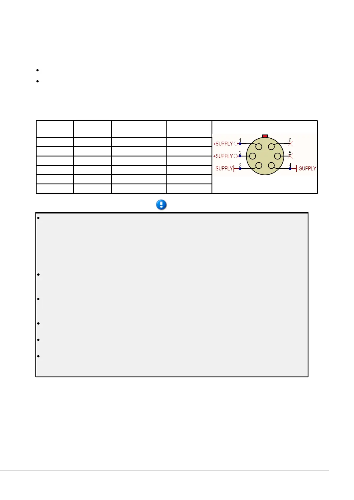
Note that the cumulative current for all connected devices flows through the CAN-bus power
supply lines. Since LEMO plugs are nominally designed to take 2A rated current per pin, a
maximum of 12 imc CANSAS modules should be supplied via the CAN-bus connection (with 12 V
supply voltage and approx. 4W consumption per module, 1A cumulatively flows in the 3 modules).
If commercially available 10-pin LEMO-cables are used, which tend to have high Ohm-counts,
voltage loss in the lines must be taken into consideration (the input voltage measured at the
module must not be less than 10 V!). To avoid that problem, choose a higher voltage, e.g. 24 V.
The connectors at the 6-pin LEMO socket and those for the CAN-bus are not connected internally
but are separated from each other by diodes. Therefore, make sure that the imc CANSAS module is
supplied with power via only one of the two possible ways!
The DC-supply inputs on the device itself (LEMO-socket) are galvanically isolated, i.e. isolated from
the housing! If a imc CANSAS-SL is powered by an isolated DC-voltage source (e.g., battery), use
the shielding of the supply plug or CAN-Bus plug to ground the device.
Also, all signal leads to imc CANSAS-SL must be shielded and the shielding grounded (electric
contact between the shielding and the plug housing).
Note when arranging the power supply that the starting current is greater than the long-term
current. Also observe the remarks on CAN-bus wiring above.
The imc CAN-bus connectors made for imc devices do not meet imc CANSAS-module specs, but
can under certain circumstances be modified by imc to do so. Please contact our customer support
if interested.