DAC8 analog outputs 287
imc CANSAS Users Manual - Doc. Version 1.9 - 05.12.2014© 2014 imc Meßsysteme GmbH
6.6.4 Message Mapping
To begin, the expected numerical range is to be defined. The available choices for Data type include
signed and unsigned integers and a digital bit. Specify the resolution of the numbers as the No. of bits (8,
12 or 16 bits). The number's position within the message must also be determined, meaning in which
Byte and at which of the Byte's bits. For the scaling, the selected Unit is entered in the dialog's lower
portion. The scaling Factor for a 16-bit quantity is computed thus:
maximum value – minimum value
65535
maximum value – minimum value
32767-(-32767)
Offset = min value - scaling factor * (-32767)
The Initial value upon activation is outputted on the output channel until the first CAN-Bus message is
received. As soon as a CAN-Bus message arrives, a new value is computed for the output in accordance
with the specified transformation operation, and this new value is outputted in analog form. This value
also retains its validity until arrival of a subsequent message.
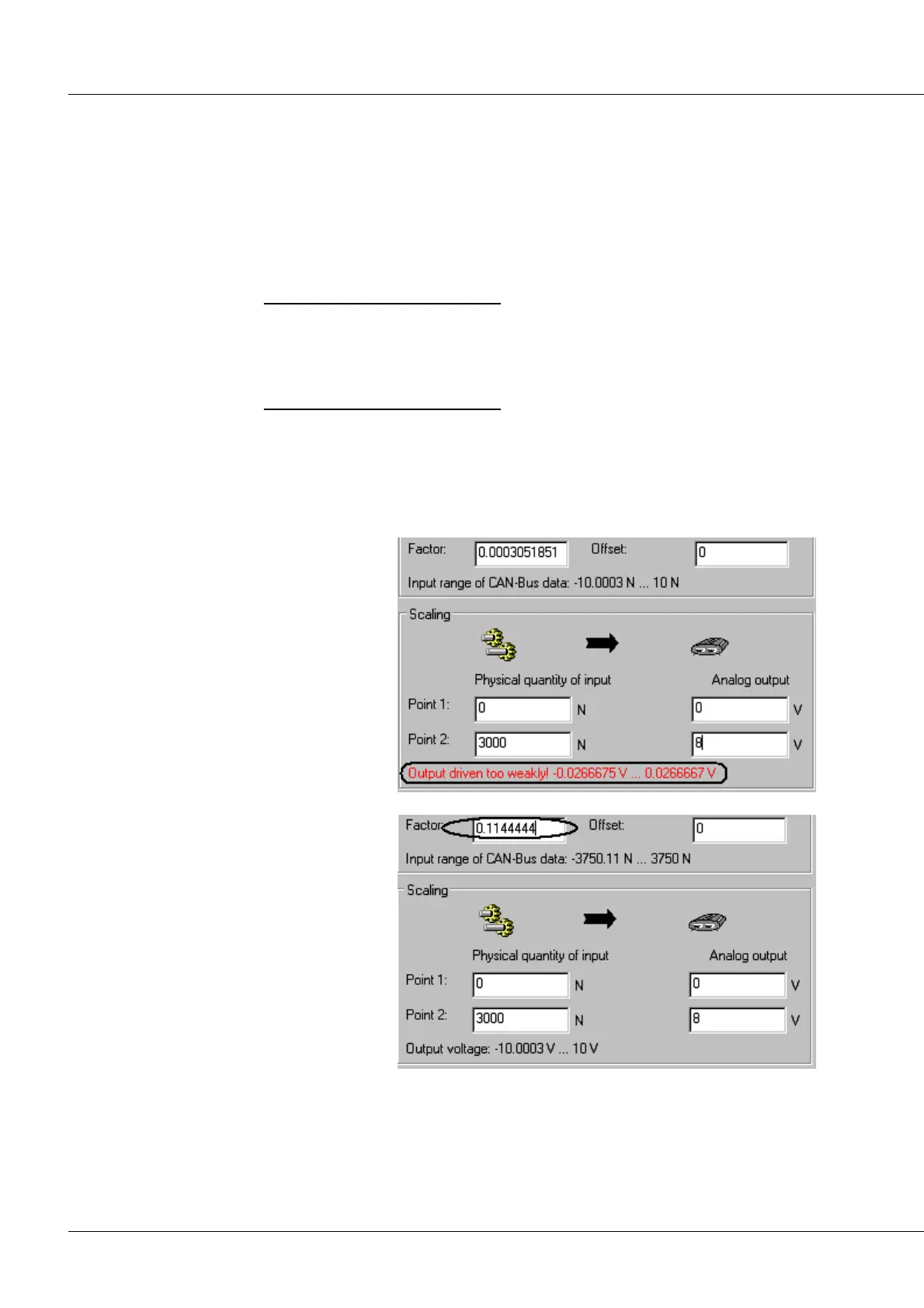
The value range on the CAN-bus, set by
the control Analog output, is between 0
V and +8 V in the example shown. The
physical input quantity has been set to
range from 0N to 3000N. Taken together
with the scaling factor specified in the
control higher up in the dialog, the
resulting possible output voltage range is
–2,667 V to +2,667 V. This means that
the maximum output voltage range isn't
being utilized.
DAC output is driven too weakly
For ideal utilization of the DAC, the
scaling factor must be selected to result
in an output range of 10 V to +10V:
Although it is possible to set an output
voltage range of, for instance, -20 V to
+20 V, but any specification over ±10 V
will be limited to ±10 V.
DAC output is driven perfectly