UNI8: universal 433
imc CANSAS Users Manual - Doc. Version 1.9 - 05.12.2014© 2014 imc Meßsysteme GmbH
6.21 µ-CANSAS-V1
1-channel voltage measurement amplifier
1 channel on a 8-Pin Phoenix MPT0,5/8
connected depending on input range either via +IN_60 V with
divider (2..60V) or via +IN_1 V without divider (0,1..1V) and -
IN_COM
Technical data imc µ-CANSAS-V1.
The single-channel module imc µ-CANSAS-V1 was designed to
be used in very warm environments. It serves to capture
voltages ranging from ±100 mV to ±60 V. The module
provides a sensor supply voltage of 5 V or 10 V. Interference
frequency components can be canceled by means of various
filter types. The zero-taring capability enables the module to
compensate for offsets.
Synchronization is performed exclusively as Slave according to the CAN1-protocol and is provided
under the node Special functions.
Beside working with CAN-bus per default, the module is also configurable as CANopen module.
The functions of the LEDs are described in section imc CANSAS blinking codes.
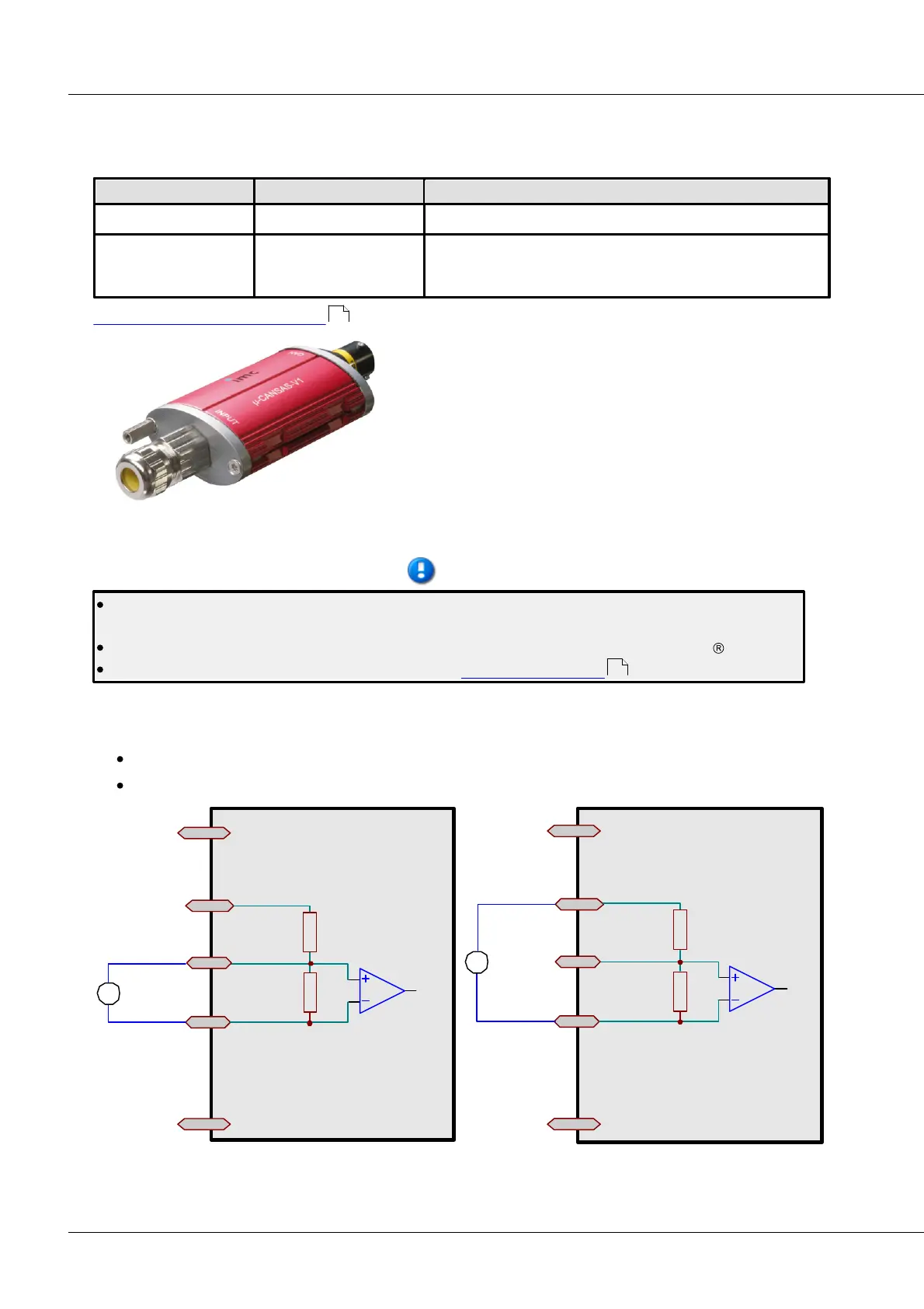
6.21.1 Voltage measurement
Voltage: ±60 V ... ±2 V connection via +IN_60 V and -IN_COM
Voltage: ±1 V ... ±100 mV connection via +IN_1V and -IN_COM
+IN_60V
-IN
+SU PPLY
-SUPPLY
+
-
+IN_1V
Connection diagram for voltage up to ± 1V
+IN_60V
-IN
+SU PPLY
-SUPP LY
+
-
+IN_1V
Connection diagram for voltage > ± 1V
512
220