496 General Technical Specs
imc CANSAS Users Manual - Doc. Version 1.9 - 05.12.2014© 2014 imc Meßsysteme GmbH
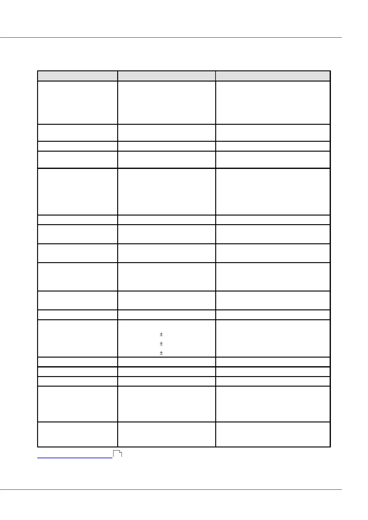
7.17 PWM8
Datasheet Version 1.5 (8 digital outputs)
4-channel-group isolated to the other group
as well as to supply and CAN-bus.
No isolation within a group.
Separate voltage supply for both 4-channel-
groups.
Open-Drain output
TTL-output
each channel has one open-drain and one
TTL output.
common setting for each channel group
Time resolution of
Measurement
counter frequency 32 MHz
(primary sampling rate)
60 ns
90 ns
160 ns
290 ns
550 ns
10 kHz to 500 Hz
500 Hz to 250 Hz
250 Hz to 120 Hz
120 Hz to 60 Hz
60 Hz to 30 Hz
TTL: 5 V
Open-Drain: <30 V
internal supply
external supply
5 V/ 30 mA per plug
(VCC_1_4 and VCC_5_8)
Additionally to supply of outputs
TTL (High-level): <10 mA
TTL (Low- level): <10 mA
Open-Drain (Low- level): <1400 mA
TTL: < 6/ 16 ns
open-drain: < 10/ 20 µs
Isolation:
CAN-Bus
supply
analog output
to housing (Chassis)
nominal; testing: 300 V (10 s)
nominal; testing: 300 V (10 s)
nominal; testing: 300 V (10 s)
2x DSUB-15
8x ITT VEAM
2x DSUB-9
PHOENIX (MC 1,5/4STF-3,81)
outputs: PWM8, -K-PWM8
-L-PWM8-V
CAN (in/out)
supply
35 x 111 x 90 mm
81 x 128 x 145 mm
75 x 111 x 145 mm
CANSAS-PWM8
CANSAS-K-PWM8
CANSAS-L-PWM8-V
Module description PWM8
367