PWM8 pulse width modulation outputs 369
imc CANSAS Users Manual - Doc. Version 1.9 - 05.12.2014© 2014 imc Meßsysteme GmbH
6.17.3 Delay time
The delay time varies between the arrival of a new PWM-value in a CAN message and the PWM output. It
depends on the internal condition of the module. The time can be calculated like this:
T_delay = T_process + T_period
T_process = A value between 0,2 ms ...1 ms. It is the time to get the CAN-bus message, to proceed and
send it to the PWM output.
T_period = 0...1/F_output
F_output is the selected output frequency (cycle duration of the PWM-signal). A new PWM-value can be
proceeded not before the previous cycle is over.
Example: The output frequency is 10 kHz (= 0,1 ms PWM-cycle duration).
T_delay_min = 0,2 ms + 0 ms = 0,2 ms
T_delay_max = 1 ms + 0,1 ms = 1,1 ms
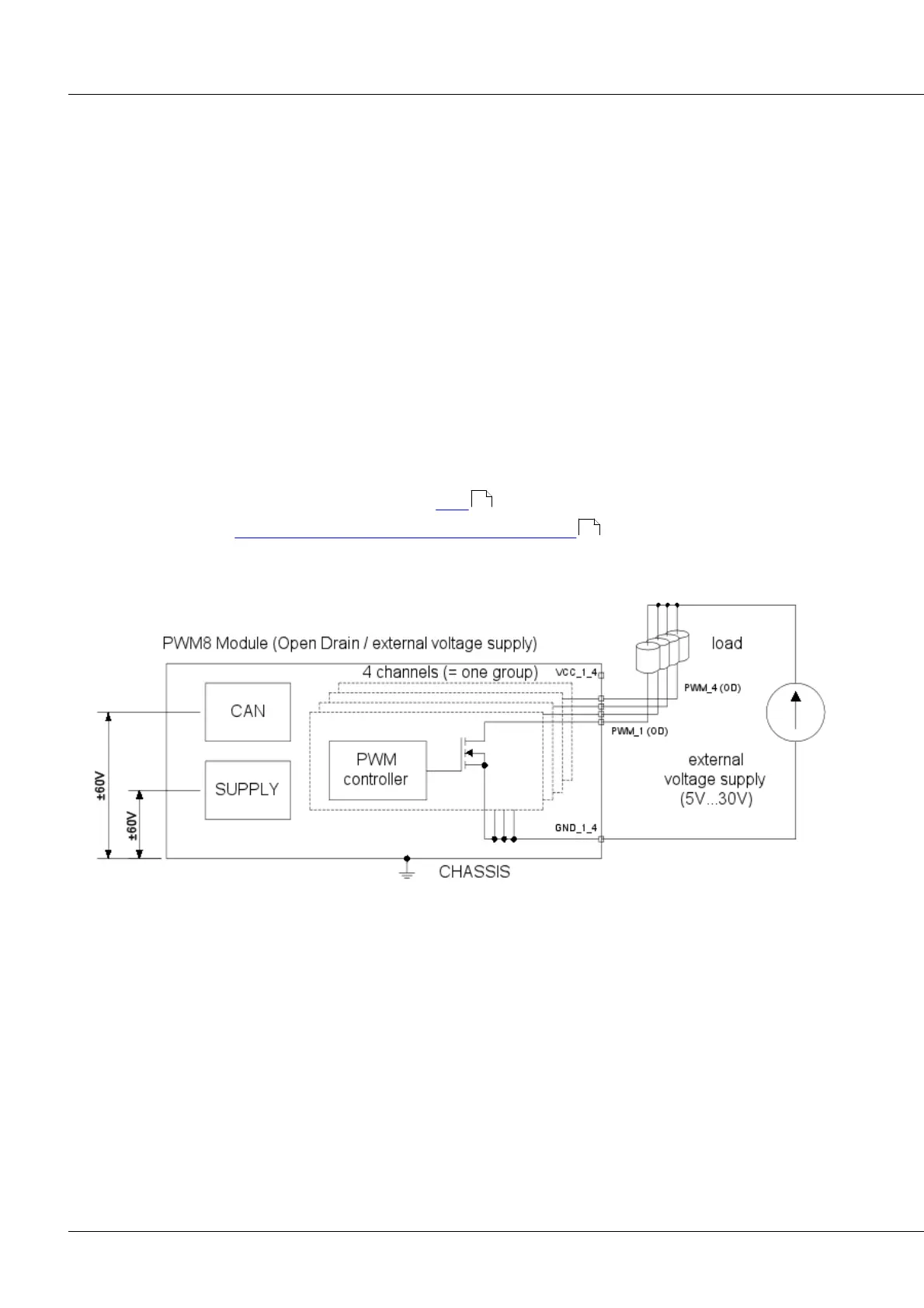
6.17.4 Connection PWM8
For the pin assignment of the DSUB-15 plugs see here .
Pin configuration of imc CANSAS-L-PWM8-V with ITT VEAM terminals . The imc CANSAS-K-PWM8-BNC
is equipped with BNC connectors.
Outputs configured as Open drain with external voltage supply
538
551