Sensor Supply Module 519
imc CANSAS Users Manual - Doc. Version 1.9 - 05.12.2014© 2014 imc Meßsysteme GmbH
7.27 Synchronization line
Technical specs of the imc CANSAS modules' synchronization line
High-level output voltage (“Master mode”)
Low-level output voltage (“Master mode”)
High-level output current (“Master mode”)
High-level Input Voltage (“Slave mode”)
Low-level Input Voltage (“Slave mode”)
7.28 Tables and diagrams
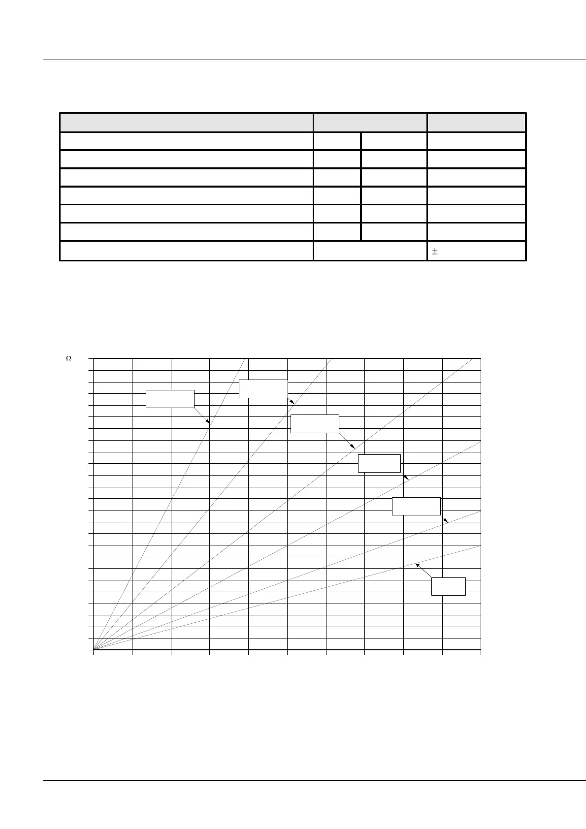
7.28.1 Cable resistance as function of length and cross-section
0
2
4
6
8
10
12
14
16
18
20
22
24
26
28
30
32
34
36
38
40
42
44
46
48
50
0.14 mm²
0.22 mm²
0.35 mm²
0.5 mm²
0.75 mm²
1 mm²
0.0 0.1 0.2 0.3 0.4 0.5 0.6 0.7 0.8 0.9 1.0
km
Nomogram to determine cable resistance as function of one w ay distance and cross-section of copper cables