452 Properties of the Modules
imc CANSAS Users Manual - Doc. Version 1.9 - 05.12.2014© 2014 imc Meßsysteme GmbH
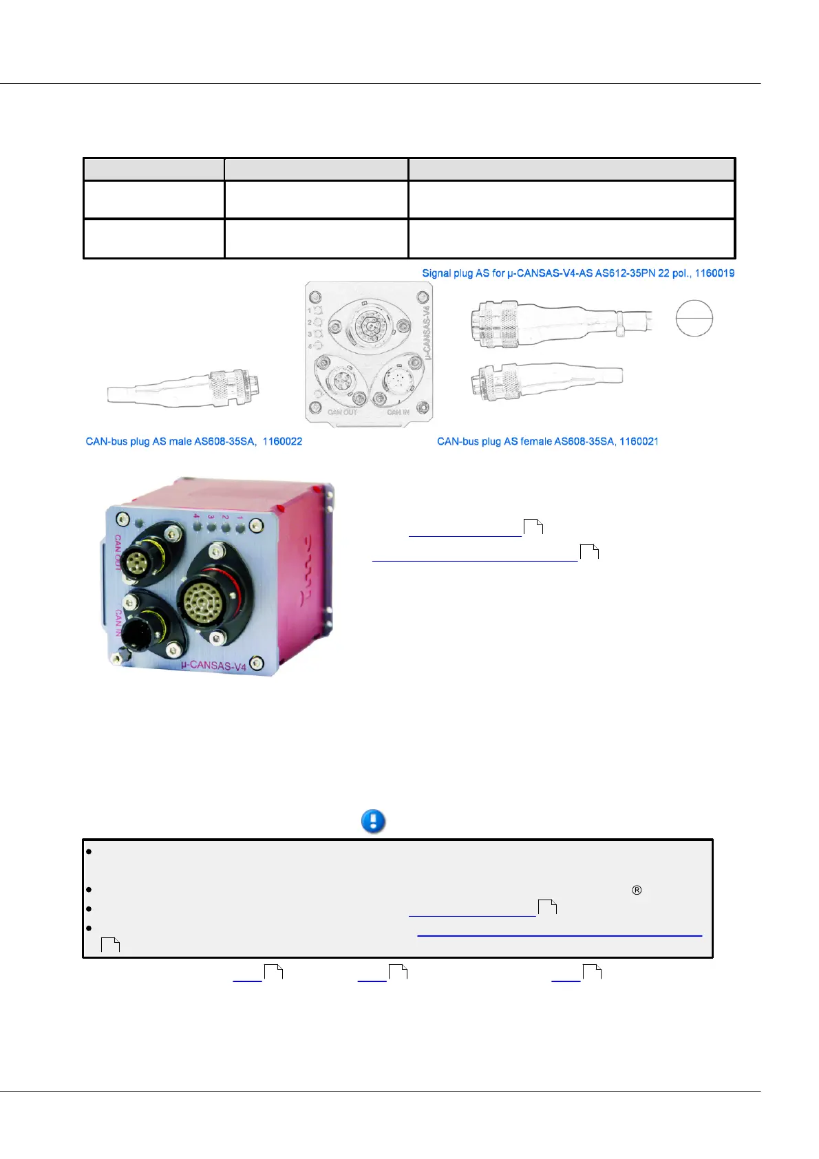
6.24 µ-CANSAS-V4
4-channel voltage measurement amplifier
4 channels on one 22-Pin Autosport terminal
(type AS212-35SN)
2 connectors depending on voltage input range (+IN_60V
and +IN_1V)
The imc µ-CANSAS-V4 comes with four integrated imc µ-
CANSAS-V1 channels.
For the configuration of the channels, see the description
of the imc µ-CANSAS-V1 .
Technical data imc µ-CANSAS-V4.
Make note of the channels’ message mapping. The channels can be sent together in one message in the
customary manner or divided among multiple messages as desired. With each imc µ-CANSAS channel
having a message length of 16 bits, all 4 channels can be sent by the HUB in one message. If a message
length higher than 16 Bit (24 or 32 Bit) is set, then the 4 channels need to be distributed over 2 messages.
Synchronization is performed exclusively as Slave according to the CAN1-protocol and is provided
under the node Special functions.
Beside working with CAN-bus per default, the module is also configurable as CANopen module.
The functions of the LEDs are described in section imc CANSAS blinking codes.
Please note the hint concerning double values with imc CANSAS modules and imc DEVICES/Studio
.
CAN-Bus connector see here . Cables see here . Sensor connector see here .
433
512
220
41
528 530 562