344 Properties of the Modules
imc CANSAS Users Manual - Doc. Version 1.9 - 05.12.2014© 2014 imc Meßsysteme GmbH
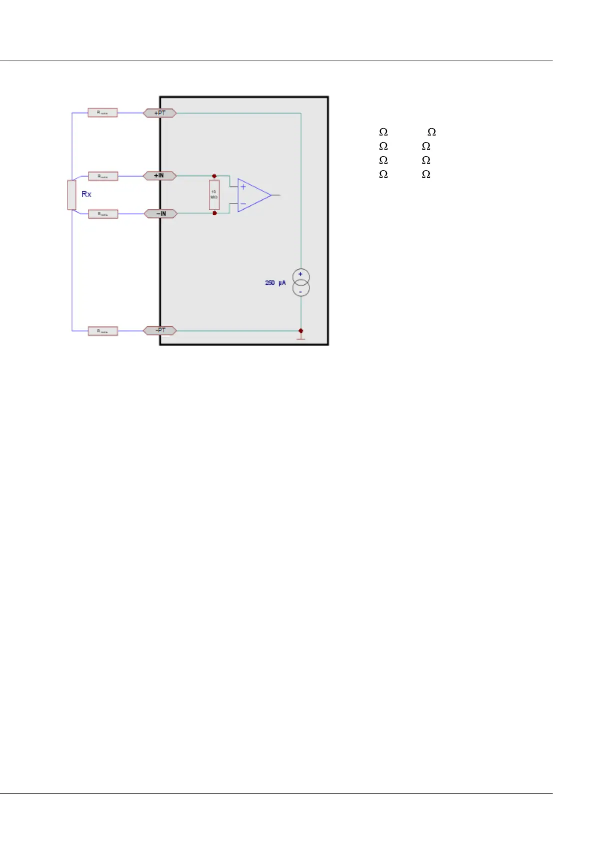
6.14.4 Resistance measurement
configuration for resistor measurement
Measurement ranges:
0 to 1000
0 to 500
0 to 250
0 to 150
Each resistor is fed by a separate current source with approx. 250 µA. The measurement uses 4-wire
configuration.
The resistor is supplied by 2 lines (+I, -I). The other two measurement inputs (+IN, -IN) serve as Sense-
leads. By using the Sense-leads, the voltage at the resistor itself can be determined precisely. The voltage
drop along the conducting cable thus does not cause any measurement error.
Probe-breakage recognition:
The indicated measurement value changes to zero if the connection between +I and +IN is broken. If only
the connection to the resistor at +IN is broken, the indicated value is the input range end value.
6.14.5 Bandwidth
The channels' max. sampling rate is 1 kHz (1 ms). The analog bandwidth is 440 Hz (-3 dB).