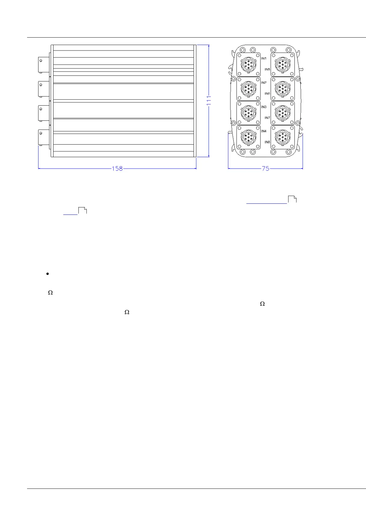
UNI8: universal 409
imc CANSAS Users Manual - Doc. Version 1.9 - 05.12.2014© 2014 imc Meßsysteme GmbH
To supply external sensors or bridges the module is equipped with a sensor supply module .
Supports TEDS (Transducer Electronic Data Sheets (IEEE 1451)
The measurement inputs whose terminals are DSUB plugs (ACC/DSUB(M)-UN2) are for voltage, current,
bridge PT100 and thermocouple measurements. They are non-isolated differential amplifiers. They share
a common voltage supply for sensors and measurement bridges.
6.20.1 Voltage measurement
Voltage: ±50 V to ±5 mV; DSUB-plug: ACC/DSUB-UNI2
Within the voltage ranges ±50 V and ±20 V, a voltage divider is in effect; the resulting input impedance is
1 M .
By contrast, in the voltage ranges ±10 V and ±5 mV, the input impedance is 20 M . For the deactivated
device, the value is approx. 1 M .
In the input ranges <20 V, the common mode voltage* must lie within the ±10 V range. The range is
reduced by half of the input voltage. The input configuration is differential and DC-coupled.
*The common mode voltage is the arithmetic mean of the voltages at the inputs +IN and -IN, referenced to the
device ground. For instance, if the potential to ground is +10 V at +IN and +8 V at -IN, the common mode voltage is
+9 V.
423
232