412 Properties of the Modules
imc CANSAS Users Manual - Doc. Version 1.9 - 05.12.2014© 2014 imc Meßsysteme GmbH
6.20.2 Bridge measurement
Measurement of measurement bridges such as strain gauges.
The measurement channels have an adjustable DC voltage source which supplies the measurement
bridges. The supply voltage for a group eight inputs is set in common. The bridge supply is asymmetric,
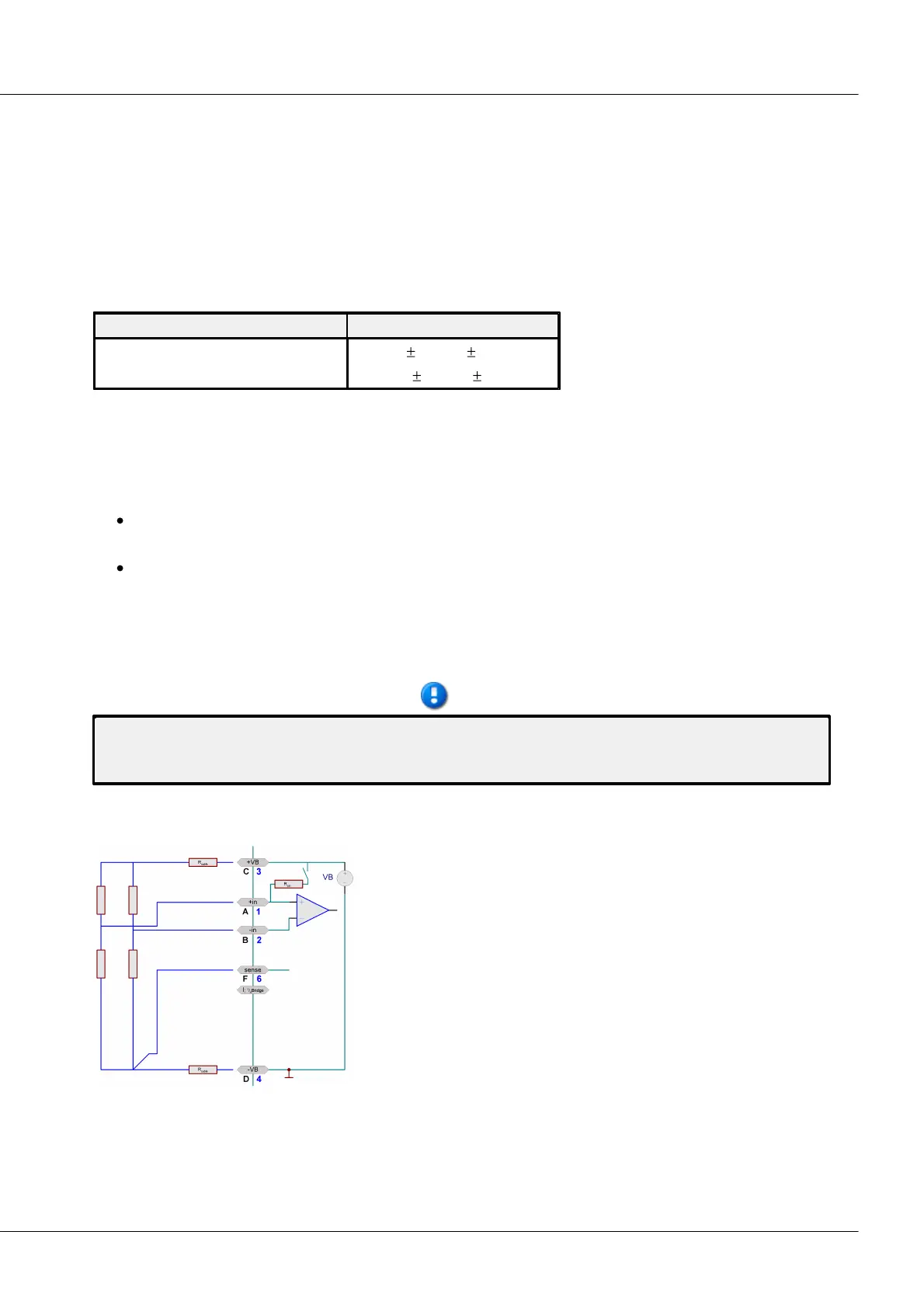
e.g., for a bridge voltage setting of VB=5 V, Pin +VB (C) is at +VB=5 V and Pin -VB (D) at -VB=0 V. The
terminal –VB is simultaneously the device's ground reference.
Per default 5 V and 10 V can be selected as bridge supply. Depending on the supply set, the following
input ranges are available:
Fundamentally, the following holds: For equal physical modulation of the sensor, the higher the selected
bridge supply is, the higher are the absolute voltage signals the sensor emits and thus the
measurement's signal-to-noise ratio and drift quality. The limits for this are determined by the maximum
available current from the source and by the dissipation in the sensor (temperature drift!) and in the
device (power consumption!)
For typical measurements with strain gauges, the ranges 5 mV/V to 1 mV/V are particularly
relevant.
There is a maximum voltage which the potentiometer sensors are able to return, in other words
max. 1 V/V; a typical range is then 1000 mV/V.
Bridge measurement is set by selecting as measurement mode either Bridge: Sensor or Bridge: Strain
gauge in the operating software. The bridge circuit itself is then specified under the tab Bridge circuit,
where quarter bridge, half bridge and full bridge are the available choices.
We recommend setting channels which are not connected for voltage measurement at the highest input
range. Otherwise, if unconnected channels are in quarter- or half-bridge mode, interference may occur
in a shunt calibration!
6.20.2.1 Full bridge
A full bridge has four resistors, which can be four correspondingly
configured strain gauges or one complete sensor which is a full
sensor internally.
The full bridge has five terminals to connect. Two leads +VB(C) and -
VB(D) serve supply purposes, two other leads +in (A) and -in(B)
capture the differential voltage. The 5th lead sense(F) is the Sense
lead for the lower supply terminal, which is used to determine the
single-sided voltage drop along the supply line.
Assuming that the other supply cable +VB (C) has the same impedance and thus produces the same
voltage drop, no 6
th
lead is needed. The Sense lead makes it possible to infer the measurement bridge's
true supply voltage, in order to obtain a very exact measurement value in mV/V.