SC16, SCI8, SCI16 voltage, current and temp. modes 379
imc CANSAS Users Manual - Doc. Version 1.9 - 05.12.2014© 2014 imc Meßsysteme GmbH
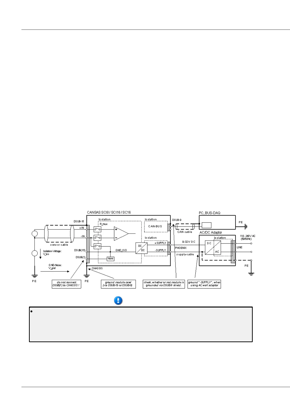
6.18.7 Isolation - Concept
The modules SCI8, SCI16 and SC16 are based on a "scanner"-concept: the channels are sampled in
succession and connected with an isolated differential amplifier. The potential levels between the signal
source and amplifier are compensated by adapting the amplifier's supply reference to the source's
common mode voltage, namely via a (low-impedance) switch.
The difference between SC16 and SCI16 consists mainly in the maximum possible isolation voltage of
their channels.
What all modules have in common is their design as an isolated differential amplifier with "block"-
isolation. Block isolation refers to the fact that the input channels are not only isolated from each other
(max. 60 V for SCI-x modules, 15 V for SC16), but additionally isolated as a group ("en bloc") from the
frame, to a degree which can even exceed the maximum channel isolation strength (max. 60 V for SCI-x
modules, 40 V for SC16). This isolation strength is known as the "maximum common mode input
voltage".
Due to the components used, the channels of SCI8 and SCI16 units are mutually isolated to a strength of
60 V.
With SC16, then, the maximum input voltage at an input pin may exceed the frame's voltage level by up
to 40 V ("max. common mode voltage"), as long as the differential between any two input pins doesn't
exceed 15 V ("max. channel isolation").
The block isolation between the CAN-bus's functional units and the "voltage supply" is defined
accordingly.
The concept of block-wise isolation allows relatively large common mode voltages, as long as the
maximum voltage differential between the module's channels is not exceeded.
The contacts +I and -I of the DSUB-15 connector are exclusively for connecting RTD (Pt100)
sensors, which have neither a galvanic connection to a different electric potential nor are
grounded. These pins are connected with the internal ungrounded module ground GND_ISO. Since
the ungrounded module is periodically connected with the common mode potentials of the signal
sources, grounding these contacts can lead to damage from short circuiting.