290 Properties of the Modules
imc CANSAS Users Manual - Doc. Version 1.9 - 05.12.2014© 2014 imc Meßsysteme GmbH
If the module's outputs are voltages (upper figure), make sure that the load impedance never falls
below 1k or that the load current never exceeds 10 mA. For current output (lower figure), a load
impedance below 500 must be set. This limits the voltage at the current's source to 10 V.
The board with the signal processor (DSP) is at internal ground potential GND. This is the module's
internal "digital ground", and is connected to the chassis as well as to the shielding of the input plug.
This internal electric potential must not "float" in relationship to the power supply or the CAN-bus.
Rather, the maximum voltage differential of 50 V to GND must not be exceeded, so GND must be held
at a suitable value. Otherwise, the module can sustain damage or malfunction. A chassis connection is
provided in the form of the shielding terminal.
It is generally recommended to connect the housing (chassis) to ground (protective grounding line).
The housing mainly consists of conduction material and is connected with GND.
The DAC8 module's analog outputs are usually connected to the voltage or current inputs of other
devices. Make sure that no ground loops are created as a consequence.
It is highly recommended that the cables containing the analog leads be shielded. The DAC8 module's
plug is provided with a shielding terminal.
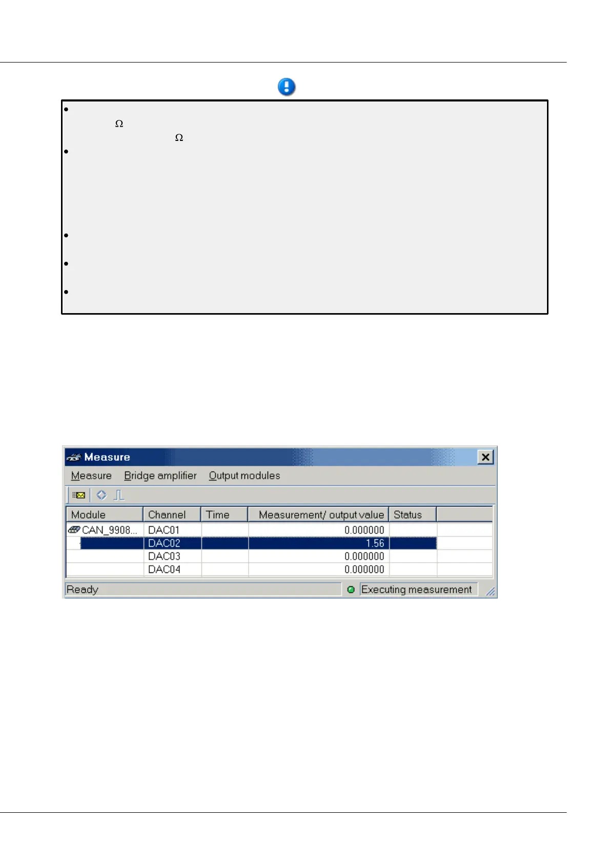
6.6.8 Taking measurements with the analog output modules
In the dialog Measure, the analog output bits of a DAC8 module are listed only if they are assigned to a
CAN-message. In such cases, the entry for the Measurement/ output value represents the signal's output
value. Upon the start of the measurement, the Power-up value is displayed. The output signal can be
influenced by editing the values in the column Measurement/ output value. By double-clicking in these
cells, the editing mode is activated, and the value for the analog bits can be toggled between 0 and 1.
When the ENTER-key is then pressed, the value is checked, accepted and sent to the module.
Measure dialog for the DAC 8 module
For output modules, the items Transfer all values and Transfer value after editing under the Output
modules menu are available.
Transfer value after editing: This function can be toggled on and off. If it is active, then any editing
performed on the entry is immediately sent to the module. If the function is off, the new value becomes
valid but is not transferred. This way, it is possible to set multiple bits and then transfer them as a unit by
using the function Transfer all values.
Transfer all values: This function transfers the output values of all output modules shown in the window
to the modules.