P8 pressure 365
imc CANSAS Users Manual - Doc. Version 1.9 - 05.12.2014© 2014 imc Meßsysteme GmbH
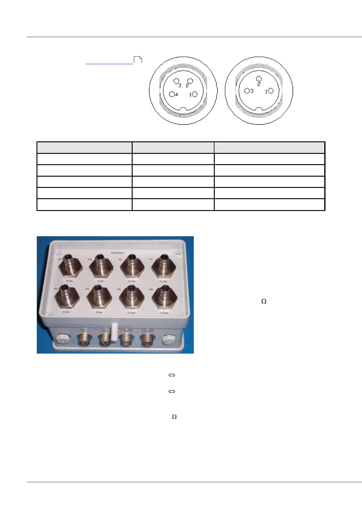
6.16.11 Pin configuration of CANSAS-P8-IP65
In contrast to the connector design
of imc CANSAS-L-P8, the pin
configuration for imc CANSAS-IP65-P8 is
as presented in the table below.
CAN connector Supply-plug
+SUPPLY (+9 V to +32 VDC)
6.16.12 CANSAS-IP65-P8-E
In contrast to the standard imc CANSAS-IP65-
P8 module, this module comes with two CAN
terminals and two Power sockets. This makes
it possible to connect the CAN-Bus through it.
The interconnections used are the Amphenol
terminals described above. The CAN terminal
and Power terminal pairs are each connected
in parallel. Internal 120 terminators of the
CAN-bus are generally omitted, but can
optionally be applied internally.
In this model, all terminals are positioned on
the top. Four channels apiece measure in the
input ranges 0-6bar and 0-10bar.
For connection to the CAN-Bus and the power supply, an adapter kit is to be used which consists of:
DSUB9
4-pin Amphenol
4-pin Phoenix
3-pin Amphenol
4-pin Amphenol or
4-pin Amphenol
3-pin Amphenol or
3-pin Amphenol
Terminations: external 4-pin Amphenol plug (120 between PIN1 and PIN2)
Reset: as with all IP65 P8
523