254 Properties of the Modules
imc CANSAS Users Manual - Doc. Version 1.9 - 05.12.2014© 2014 imc Meßsysteme GmbH
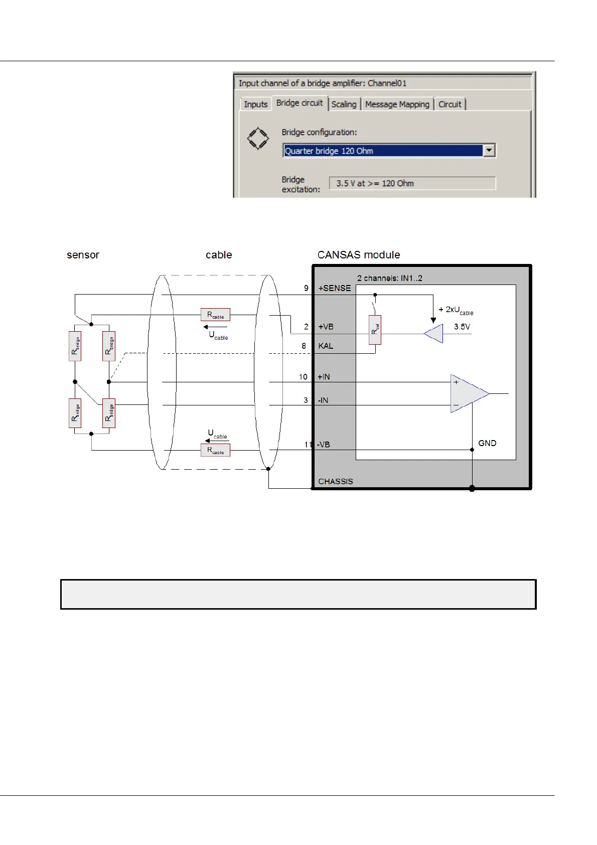
Depending on the operating type
selected, different configurations
are available as options on the
"Bridge circuit" index card.
6.1.2 Full bridge
Bridge2: block diagram full bridge
A full bridge connected to the imc CANSAS-BRIDGE2 bridge channels consists of 4 resistor arms (denoted
by R
bridge
in the block diagram). The full bridge is external, meaning that all 4 bridge resistors are outside
of the imc CANSAS module.
Setting the full bridge:
Channel0x -> Index card “Inputs” -> Measurement target combo box: “Sensor”
Channel0x -> Index card “Bridge circuit” -> Configuration combo box: “Full bridge”
The "three-wire-configuration" used in full bridge configuration to regulate the bridge voltage
guarantees the required voltage values at the sensor even if the lines to it are long and highly resistant.
This requires symmetric wiring (same resistance, therefore identical length and cross-section) of the
current conducting signal lines, as shown in thick lines in the sketch. The bridge voltage +VB is then
adjusted by the amount 2*Uk.
The internal calibration resistance can be connected to either of the two external bridge branches. In
order to prevent the cable resistance, which directly affects the bridge in a ratio of (Rb / R_kal) to the
bridge impedance, it should not be connected by a jumper wire but rather by a separate line.