IGN ignition angle measurement module 327
imc CANSAS Users Manual - Doc. Version 1.9 - 05.12.2014© 2014 imc Meßsysteme GmbH
1st - 4th cylinder monitoring
With Monitoring of Selected Cylinders activated, the cylinders are selected by means of these
parameters. Depending on the amount of cylinders to be monitored, the corresponding amount of
boxes are to be configured. For each of the cylinders to be monitored, its position in the ignition order
is specified. The particular cylinder is assigned to the 1st ignition pulse in the duty cycle, or the 2nd,
etc.
Please observe the ignition order. For instance, if the ignition order is 1-4-2-3, then the 2nd ignition is
in the 4th cylinder. Thus, if the 4th cylinder is to be monitored, the "2nd ignition impulse in the duty
cycle" must be selected.
It is assumed that the ignition impulses are distributed evenly through the duty cycle and that the
amount of ignition impulses per duty cycle is correctly configured in the associated parameter (see
above).
Example: Assume we have a 4-cylinder 4-stroke engine with a 720° duty cycle. Every 180°, there is a
firing (ignition). If the firing occurs at 30° before TDC, then the positions of the firings within the duty
cycle are at -30°, (180-30)°, (360-30)° and (540-30)°. The individual cylinders' TDC angles within the
duty cycle are 0°, 180°, 360° and 540°. The cylinder whose TDC is at 0° is considered the first in the
duty cycle.
6.11.4.1 The channel's parameters
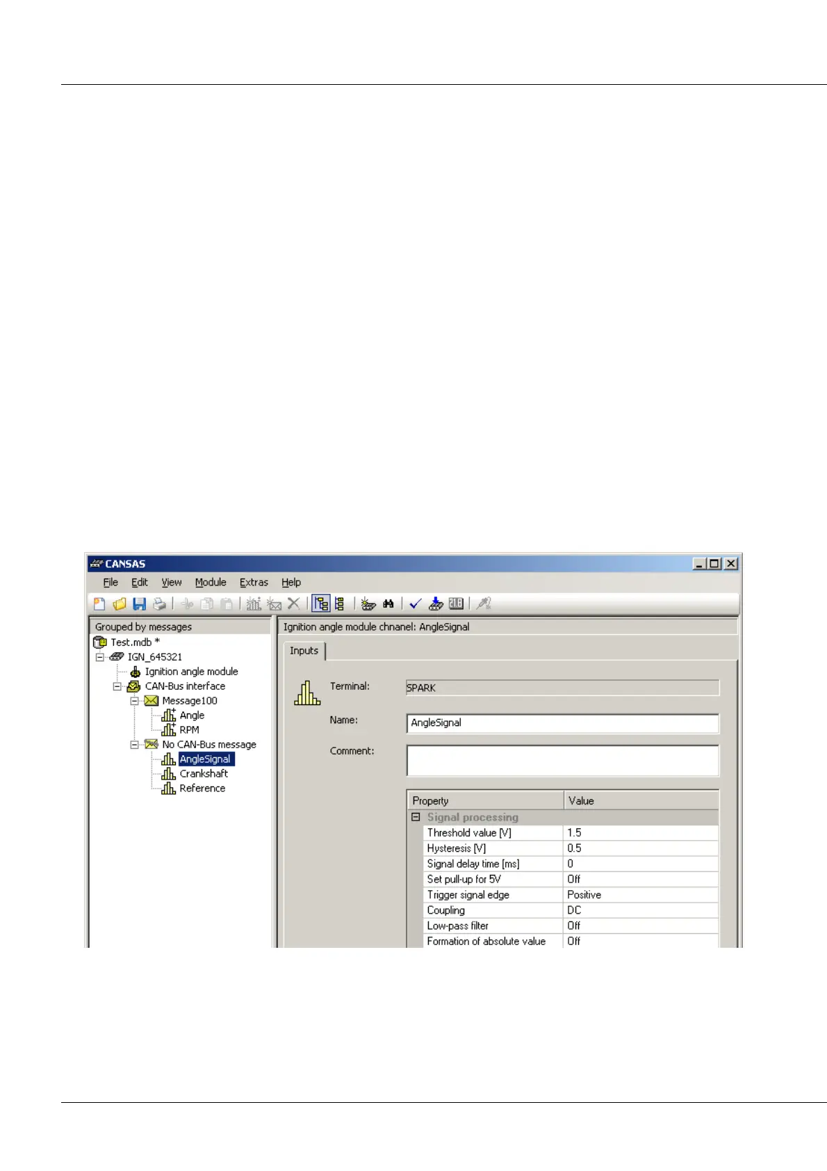
If on the left side of the imc CANSAS user interface's tree diagram, one of the input channels (ignition
signal, crankshaft, reference) in a imc CANSAS-IGN module is selected, then on the right side a table for
setting the input channel parameters appears. Multi-selection of the channels is possible.
Threshold:
A signal edge is detected when a certain signal level is crossed. This threshold value/level is stated in
Volts. It can lie between -40 V and +40 V. A resolution of 0.1V should also not be exceeded. This
means that sensible thresholds would include, for instance: 0 V, 0.1 V, 0.2 V, ...