388 Properties of the Modules
imc CANSAS Users Manual - Doc. Version 1.9 - 05.12.2014© 2014 imc Meßsysteme GmbH
6.19.1 Operating modes, isolation
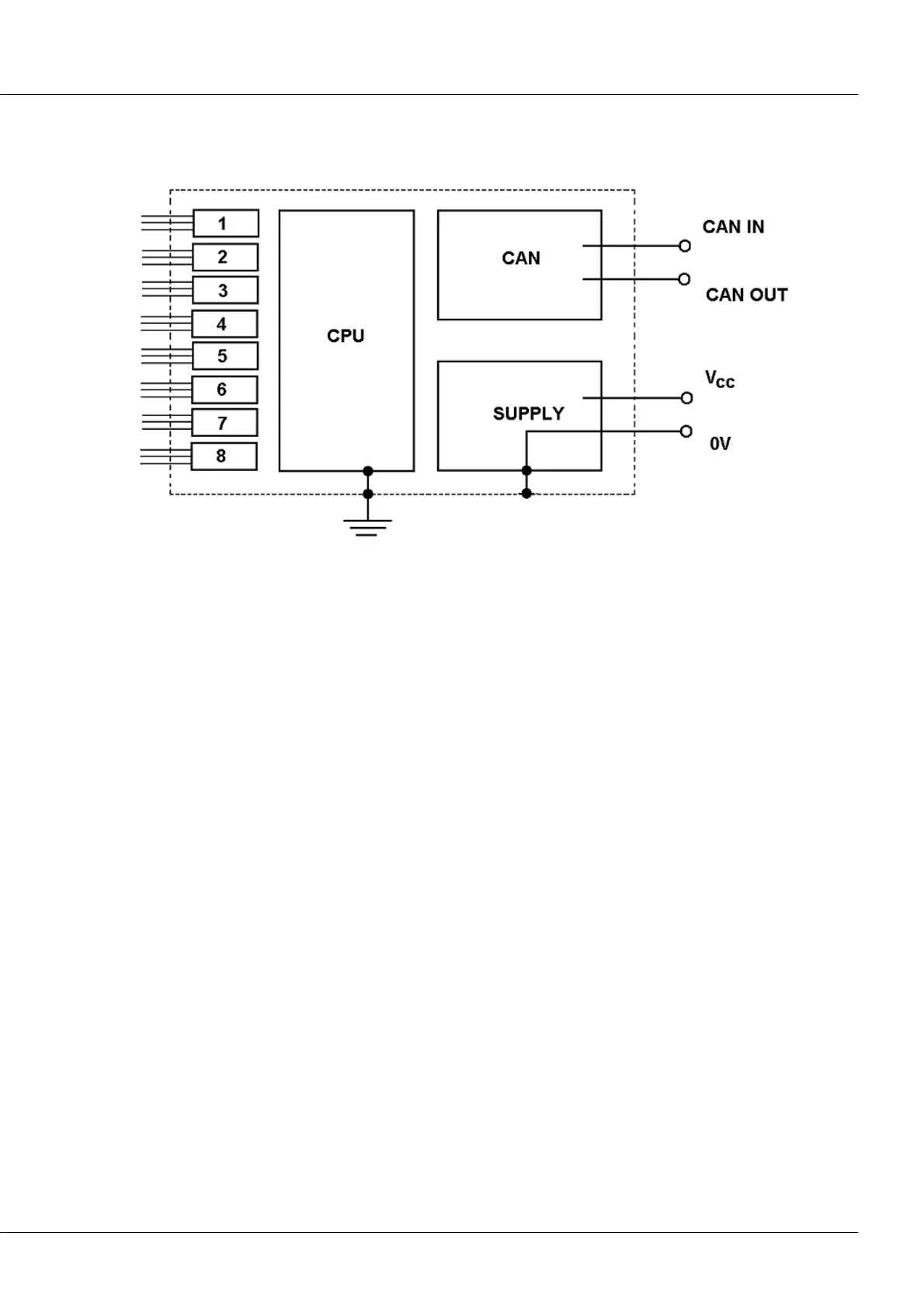
The following block diagram illustrates the module’s overall isolation scheme:
As is clearly shown, the CAN terminal and the 8 input circuits (Blocks 1..8 at the left) are isolated both
mutually and from the rest of the module, which in turn consists of module’s (not the sensors’) power
supply unit, its CPU and the chassis, which are all at the same voltage level and have a common ground.
The chassis itself is grounded. The Minus-pole of the module’s power supply is connected with the
chassis.
The imc CANSAS-SENT module has 8 inputs. One SENT-sensor can be connected at each input. Each
individual input is equipped with its own circuit. All inputs are mutually isolated, and each has its own
(and thus consequently isolated) power supply voltage. This eliminates the possibility of sensors
interfering with each other’s signals.