460 General Technical Specs
imc CANSAS Users Manual - Doc. Version 1.9 - 05.12.2014© 2014 imc Meßsysteme GmbH
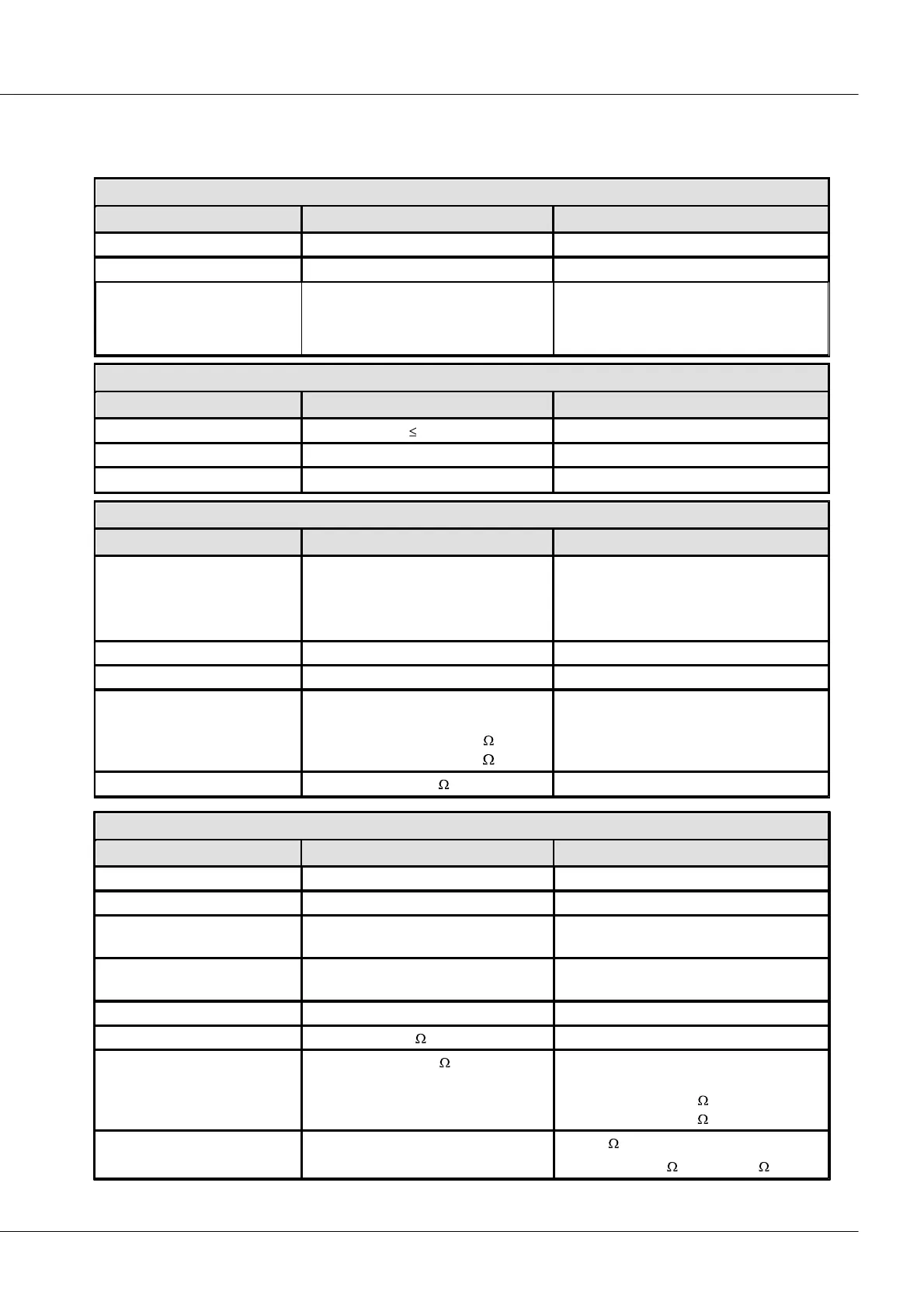
7.1 BRIDGE2
Data Sheet Version 1.2 (2-channel bridge amplifier)
Inputs, Measurement mode, Terminal connection
PHOENIX (MC 1,5/4STF-3,81)
Isolation:
input/CAN-Bus
input/power supply
input / analog
output to case (CHASSIS)
nominal; testing voltage 300 V (10 s)
nominal; testing voltage 300 V (10 s)
analog reference ground: CHASSIS
short-term, to frame (CHASSIS)
Input configuration
(configurable)
full bridge
half bridge
quarter bridge 120
quarter bridge 350
default
with wire bridge in the connector plug
internal quarter bridge completion
software selectable
full-, half-, quarter bridge
±10 mV/V, ±5 mV/V, ±2 mV/V,
±1 mV/V, ±0.5 mV/V, ±0.2 mV/V
3-wire circuit for compensation of cable
resistance (+VB, +SENSE, -VB)
releasable via CAN-bus ; "Rcal"
corresponds to:
0.30 mV/V at 120 bridge
or 0.87 mV/V at 350 bridge
28 m or max. 3% of
bridge impedance
for 120 bridge with Cu-cable
0.14 mm
2
, 130 m /m: max. 3.6