BRIDGE2: DC-bridge measurement 255
imc CANSAS Users Manual - Doc. Version 1.9 - 05.12.2014© 2014 imc Meßsysteme GmbH
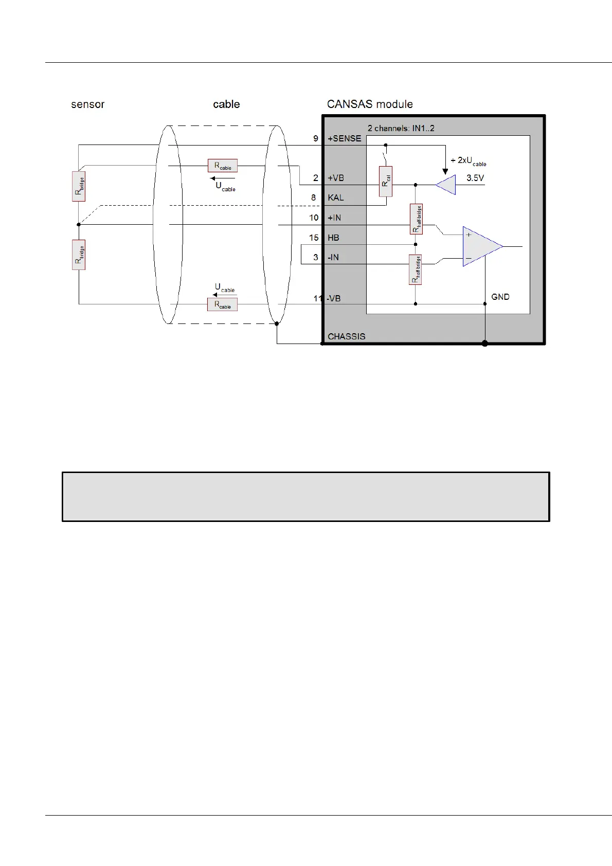
6.1.3 Half bridge
Bridge2: block diagram half bridge
In many applications, the sensor consists of only half of a full bridge, in other words of two variable
impedances. The other half must then be completed with two equal resistors of constant impedance. For
imc CANSAS-BRIDGE2 bridge channels, this half-bridge completion is internally pre-wired. It is accessible
via the terminals of the DSUB-plug as “HB1” and “HB2” and need only be connected by a jumper to the
corresponding input pin. Only one half bridge is external, in other words there are 2bridge resistors
outside of the imc CANSAS module.
Setting the half bridge:
Channel0x -> Index card “Inputs” -> Measurement target combo box: “Sensor”
Channel0x -> Index card “Bridge circuit” -> Configuration combo box: “Half bridge”