CAN-Bus connectors 523
imc CANSAS Users Manual - Doc. Version 1.9 - 05.12.2014© 2014 imc Meßsysteme GmbH
Pin configuration and power supply
8.1 CAN-Bus connectors
By default, the connector to CAN is with DSUB-9 .
imc CANSAS-SL modules are equipped with LEMO connectors .
imc µ-CANSAS modules use Autosport connectors.
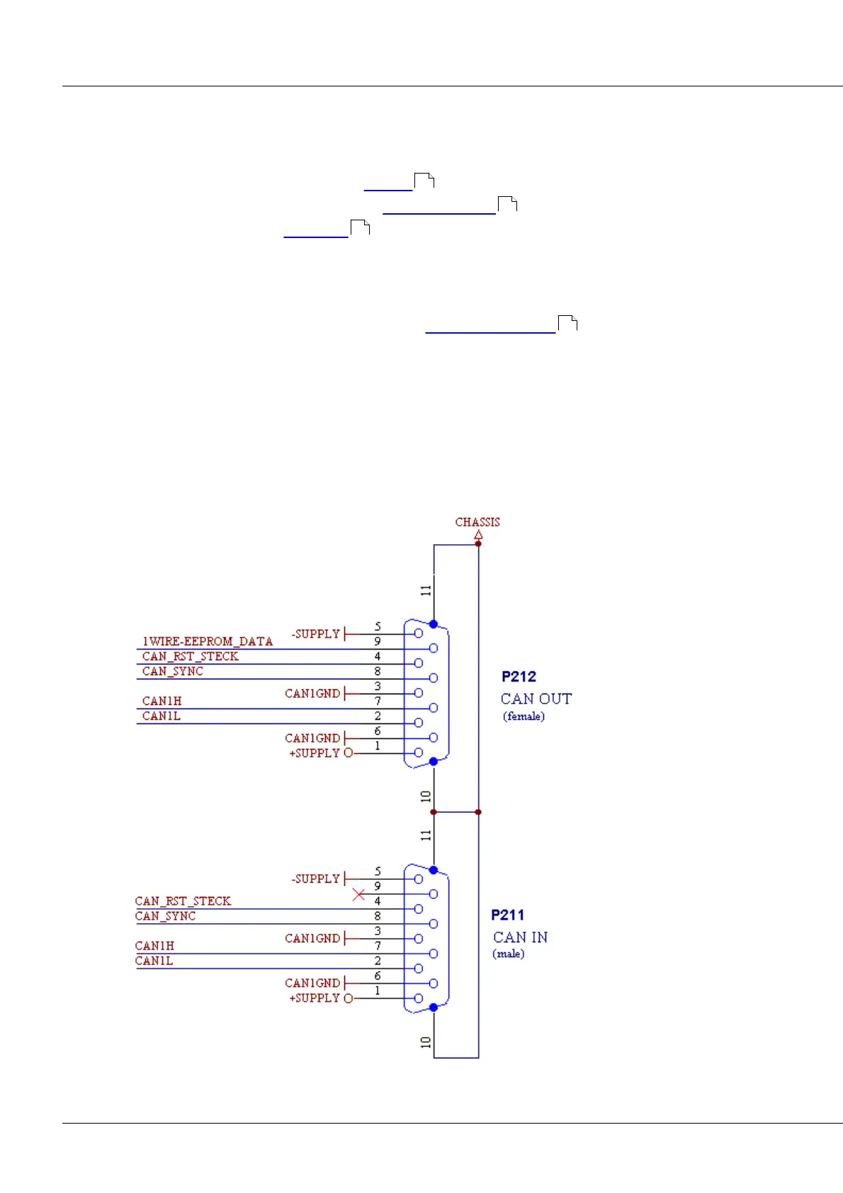
8.1.1 Standard module with DSUB-9 CAN Bus connector
Below is shown the pin configuration of the CAN-bus plug/socket set (CAN IN and CAN OUT).
A general description of the CAN-bus can be found in CAN-Bus description .
Notes on the hardware versions
Hardware Version 1: Valid for all devices shipped prior to mid-2003. (C12,ISO8, INK4, Bridge2, DI16,
DO16, DAC8). In these modules, there is no lWIRE-EEPROM_DATA connection; CAN IN is thus identical to
CAN OUT in terms of the pin configuration.
Hardware Version 2: Valid for all UNI8, P8, DO16R, C8 and all -L- modules. For all other modules, please
check in the software under General/ Version/ Hardware whether this is the version. Generally it only is
for modules shipped since late-2003.
523
526
527
37