524 Pin configuration and power supply
imc CANSAS Users Manual - Doc. Version 1.9 - 05.12.2014© 2014 imc Meßsysteme GmbH
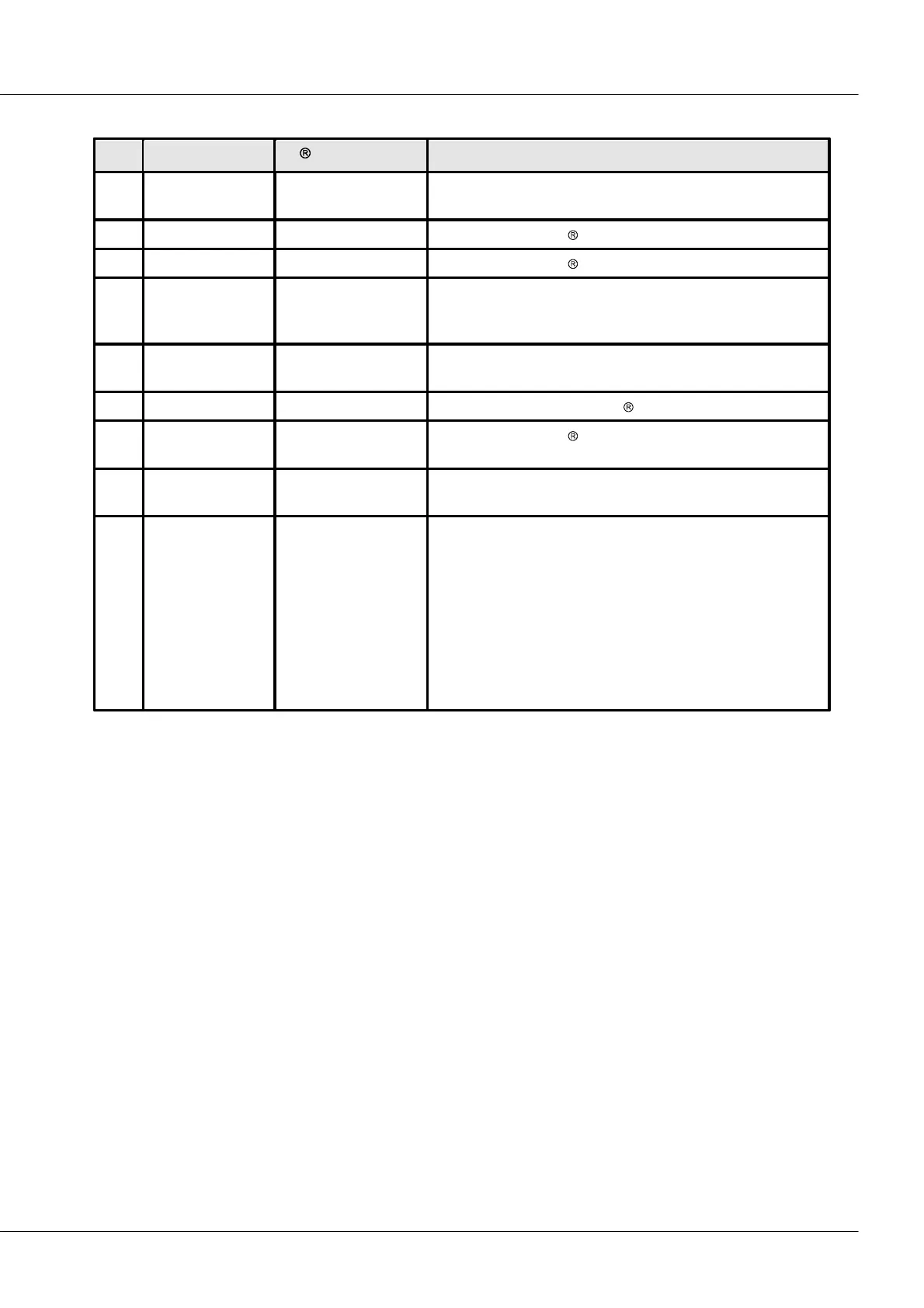
imc CANSAS-specific: + imc CANSAS voltage supply. The
module can be supplied via this connector (and Pin 5).
connected as per CiA . CAN-Bus reference ground.
imc CANSAS-specific: imc CANSAS Reset ( for startup with
Reset Connector). The Reset plug has a shortcut to PIN 3
(GND).
imc CANSAS-specific: - imc CANSAS voltage supply (Negative
pole of supply respectively. 0V).
connected to Pin 3, as per CiA
imc CANSAS-specific: Additional line for a sync signal (1 Hz).
Generally 5 V to CAN Ground.
imc CANSAS-specific: EEPROM information about mounting
position (when used in a rack)
Exists only at female CAN-OUT plug P212. Pin 9 at male CAN-
In plug is "not connected".
Pin 9 is the positive pin of the EPROM. The corresponding
minus-pole must be connected to the chassis/shield (10/11)
of the DSUB-plug.
The EPROM is not inside the module, but can be connected
external.
The two 9-pin plugs are connected to each other 1:1; thus, all connections can be fed through to the next
imc CANSAS module, but not Pin 9.
 Loading...
