BRIDGE2: DC-bridge measurement 257
imc CANSAS Users Manual - Doc. Version 1.9 - 05.12.2014© 2014 imc Meßsysteme GmbH
6.1.5 Balancing and shunt calibration
The maximum compensable range for each input range (3 mV/V are always assured; the table shows the
values achieved in practice):
There are various ways to perform balancing of imc CANSAS-BRIDGE2:
Pressing the special button on the imc CANSAS-BRIDGE2 module
Automatic balancing upon power-up of module
Balancing is triggered by a CAN-bus message.
All 3 options can be implemented in a configuration and can initiate balancing. However, if a balancing
process is currently running, any new command to perform balancing is ignored until the current process
is over. As a rule both bridge channels are balanced at once. If balancing isn't possible because the
unbalance exceeds the balance range, this can be indicated by the LEDs on the imc CANSAS-BRIDGE2
module (see Chapter Measurement technique ).
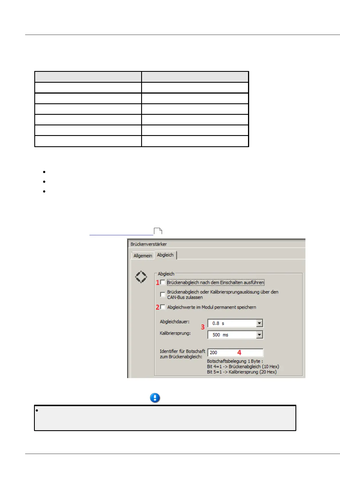
1 Bridge balance performed upon
activation of device
2 The last balancing value is
recorded in the module
3 These two values can be adjusted
as desired
4 User's choice of CAN bus-ID, e.g.
balance over CAN by Online
FAMOS
Settings for balance and shunt calibration
Note that importing a changed configuration to the module deletes any previously performed
bridge balancing and resets it to zero. Therefore, always repeat bridge balancing after importing a
configuration!
220