Measurement modes 205
imc CANSAS Users Manual - Doc. Version 1.9 - 05.12.2014© 2014 imc Meßsysteme GmbH
5.1.5 Digital Outputs (CANSAS-DO8R, -DO16, -DO16R)
These modules are for digital output. The imc CANSAS-DO16R module has 16 digital outputs, which are
switched using relais. DO16 (without "R") serves the same purpose with open collector outputs. The imc
CANSAS-DO8R module has 8 relay switches. The output signals can be set by a CAN-message or by a
calculation. The output's state upon module power-up is defined.
5.1.5.1 Outputs
All the outputs have switching times. For the module DO8R they can be up to 4 ms, for DO16 under 0,1
ms. In both cases the switching time is different for switching the output on or off.
In DO16R, each terminal's 8 outputs have a shared reference ground and are thus not isolated from each
other. They are isolated from the 8 outputs of the other terminal, chassis, power supply and the CAN-
bus.
5.1.5.2 Connecting an output signal with a CAN-message
If a certain output bit is to be set by a CAN-message, that output bit must be positioned in a message.
The output bit's module tree entry can be positioned as desired by Drag & Drop in the module tree at any
position in the message or under "No CAN-bus message". Note that the tree must be grouped by
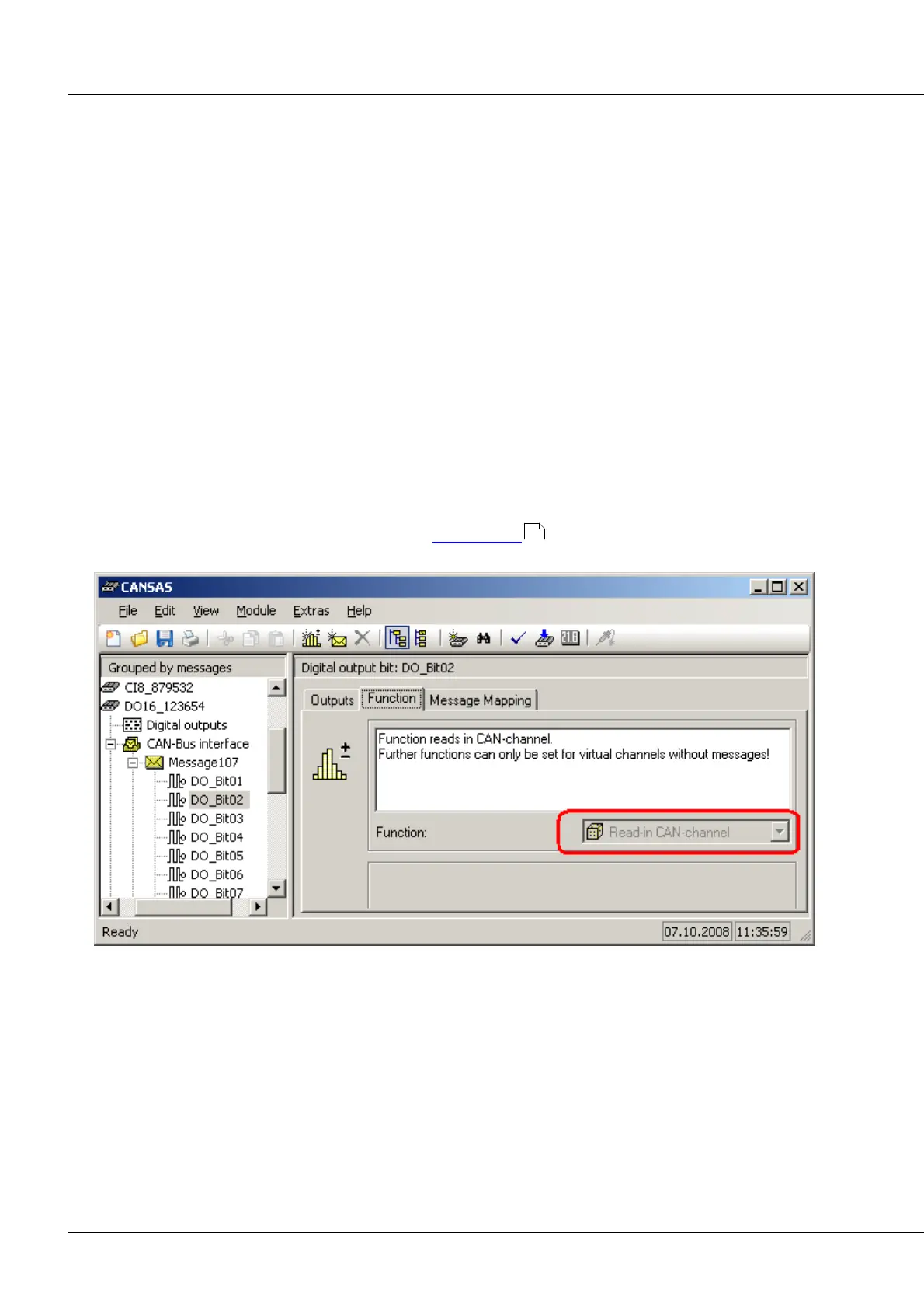
message for this to work (see View menu, item "Grouped by" ). Then the output bit function Read-in
CAN-channel is unalterably active.
output bit DO_Bit02 is in CAN-message Message01.
The function is always set to"Read-in CAN-channel".
On the index card Message mapping, the data type, start byte and start bit can be specified. It makes
sense to select digital bit as the data type for the digital output signal. The settings for the starting byte
and starting bit specify which bit in the message determines the output signal value.
In the lower portion of the card, the output signal's state upon activation of the module can be specified.
88