UNI8: universal 413
imc CANSAS Users Manual - Doc. Version 1.9 - 05.12.2014© 2014 imc Meßsysteme GmbH
Please note that the maximum allowed voltage drop along a cable may not exceed approx. 0.5 V. This
determines the maximum possible cable length.
If the cable is so short and its cross section so large that the voltage drop along the supply lead is
negligible, the bridge can be connected at four terminals by omitting the Sense line.
6.20.2.2 Half bridge
A half bridge may consist of two strain gauges in a circuit or a
sensor internally configured as a half bridge, or a potentiometer
sensor. The half bridge has 4 terminals to connect. For information
on the effect and use of the sense (F) lead, see the description of
the full bridge .
The amplifier internally completes the full bridge itself, so that the
differential amplifier is working with a full bridge.
It is important that the measurement signal of the half bridge is
connected to +IN (A). The IN (B) access leads to implausible
measured values and influences the neighbor channels.
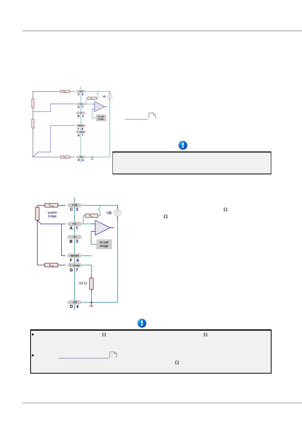
6.20.2.3 Quarter bridge
A quarter bridge can consist of a single strain gauge resistor.
UNI8 internally completes an additional 120 that can be
switched to a 350 quarter bridge.
For quarter bridge measurement, only 5 V can be set as the
bridge supply.
The quarter bridge has 3 terminals to connect. Refer to the
description of the full bridge for comments on the Sense lead.
However, with the quarter bridge, the Sense lead is connected to
+in(A) and sense(F) jointly.
If the sensor supply is equipped with the option “±15 V”, a
quarter bridge measurement is not possible. The pin I_1/4Bridge
for the quarter bridge completion is used for –15 V instead.
By default comes with a 120 internal bridge completion resistor. A 350 completion resistor is
alternatively possible for the purpose of quarter bridge measurement. When using this option, the
scope of available functions is limited:
No direct current measurement with the standard included connector ACC/DSUB-UNI2 is possible,
but only with the optional ACC/DSUB-I2 connector with a 50 shunt resistor (differential
measurement).
412
416