Sampling rates: Scanner concept 215
imc CANSAS Users Manual - Doc. Version 1.9 - 05.12.2014© 2014 imc Meßsysteme GmbH
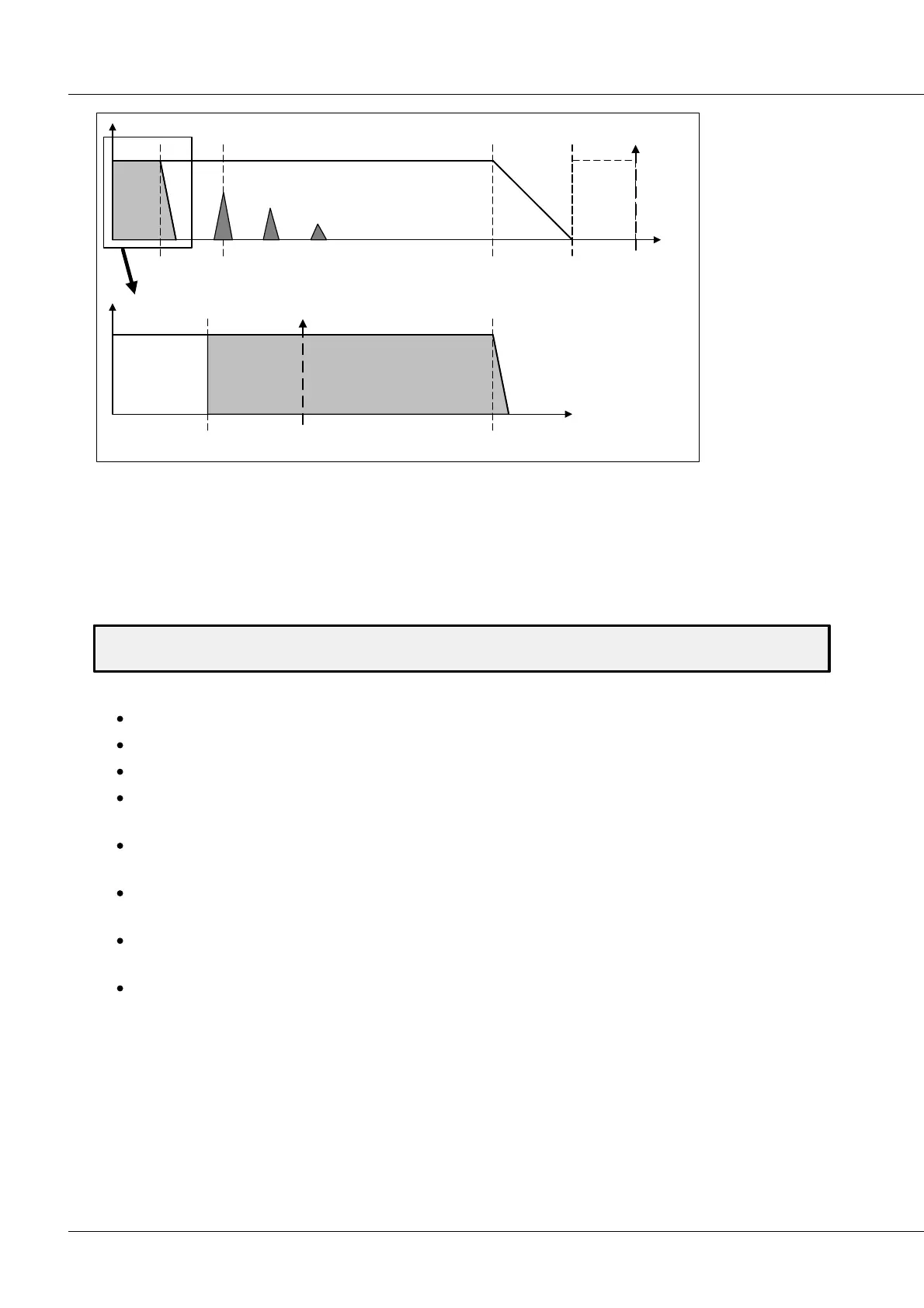
G
f
14 Hz filter
(transversal)
50 ms burst
50 Hz
Nois e
8.6 kHz
AAF
40 kHz
sample
ADC
20 k Hz
Nyquis t
(ADC)
G
f
0.5 Hz
Nyquist (k-Rate)
1 Hz
Sam ple (k )
14 Hz
filter bandw idth
Aliasing:
-> non relevant
no noise between
0.5Hz .. 14Hz
Burst-measurement: 40 kSamples (Sigma-Delta ADC, BW 8,6 kHz): Aliasing-free!
Aliasing-
free
band of
interest
effective user channel rate: 1 Hz @SC16, SCI16 (2 Hz @SCI8)
5.3 CAN-Bus: Delay times
Here we will deal with the question of how much delay there is between a measured value's acquisition
and when it is outputted on the CAN-Bus. This is an important issue if the module is used for process
control purposes, in which the system is to respond to the currently valid measurement value. For
measurement tasks only involving data recording, the delay time is negligible.
The delay time is the time difference between a signal's sampling time and the instant and when the
corresponding message is outputted on the CAN-bus.
The following time intervals each make a contribution:
The signal's propagation time through the input amplifier and the analog anti-aliasing filter.
Delay time of the analog/digital converter
Duration of the digital processing, e.g. correction and digital filtering
Construction of the CAN-message. This involved waiting for acquisition of all measurement values
to be included in the CAN-message.
Waiting period until the CAN-controller has sent its last message and this message has been entered
into the CAN-controller's register.
The CAN-controller next tries to take the next best opportunity to put its message onto the CAN-
Bus. This involves waiting for transmission disturbances and higher-priority messages to pass.
The actual transfer of the CAN-message. For a full message and at 500kbit/sec, this can be up to 0,2
ms.
Additional time intervals may accrue in receiving the message.
In this context, it's only possible to state the delay time till the point when the CAN-controller is prepared
to transmit the message. We assume that the CAN-Bus is undisturbed and there are no other modules
currently outputting messages on the bus; only then can a module's delay time be stated. The user can
then compute for his own CAN-configuration what delays will result from higher-priority messages.
The delay time is stated for the module's default setting. This means for four adjacent channels in a CAN-
message, starting with Channel 1. One flashing LED and no additional virtual channels.