µ-CANSAS-T1 441
imc CANSAS Users Manual - Doc. Version 1.9 - 05.12.2014© 2014 imc Meßsysteme GmbH
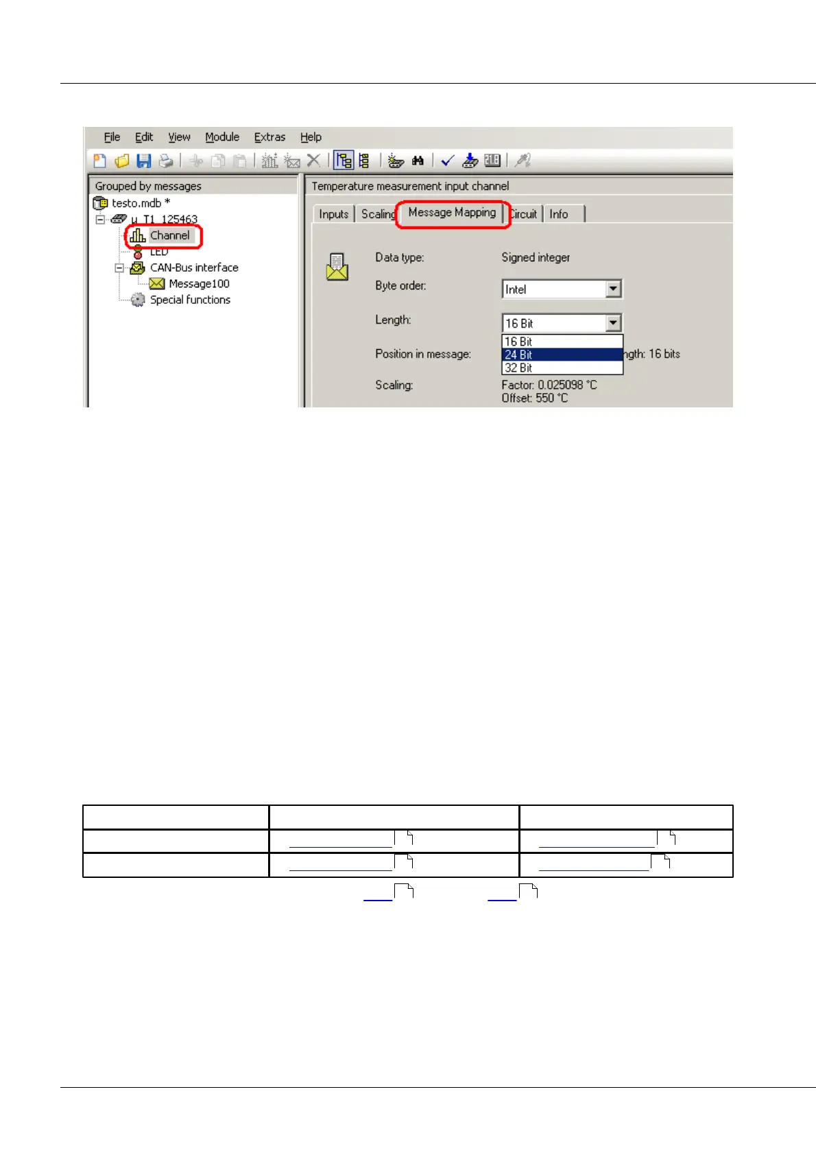
6.22.2 Message Mapping
The modules belonging to the imc µ-CANSAS group work with a maximal resolution of 24 bits. The
Message Mapping page also offers a message length of 32 bits, in which case a value in 32-bit Float
format is transferred.
If four single-channel imc µ-CANSAS modules are connected via a imc µ-CANSAS-HUB4, note the
following: if the values from four imc µ-CANSAS modules are to fit into one message, then a channel’s
length is limited to 16 bits. Since a message can transport a maximum of 8 data bytes, this amounts to
only 2 bytes per channel. If 24 bits per channel are to be used, then with HUB at least two messages must
be created for four channels.
6.22.3 Sampling interval, filter
For imc µ-CANSAS-T1, sampling rates can be set in steps of 1, 2, and 5. The available sampling interval for
the imc µ-CANSAS-B1 extends from 60s to 0,5 ms.
With imc µ-CANSAS-T1, the following filter is set:
Mean value: The output value is the mean value over (output clock rate [ms] / 500µs) values. For
temperature measurement, only averaging filtering is available.
6.22.4 µ-CANSAS-T1 connector
signal (sensor) connection
Sensor connector with Autosport AS plug see here . Cables see here .
558 528
558 529
561 530