µ-CANSAS-B4 455
imc CANSAS Users Manual - Doc. Version 1.9 - 05.12.2014© 2014 imc Meßsysteme GmbH
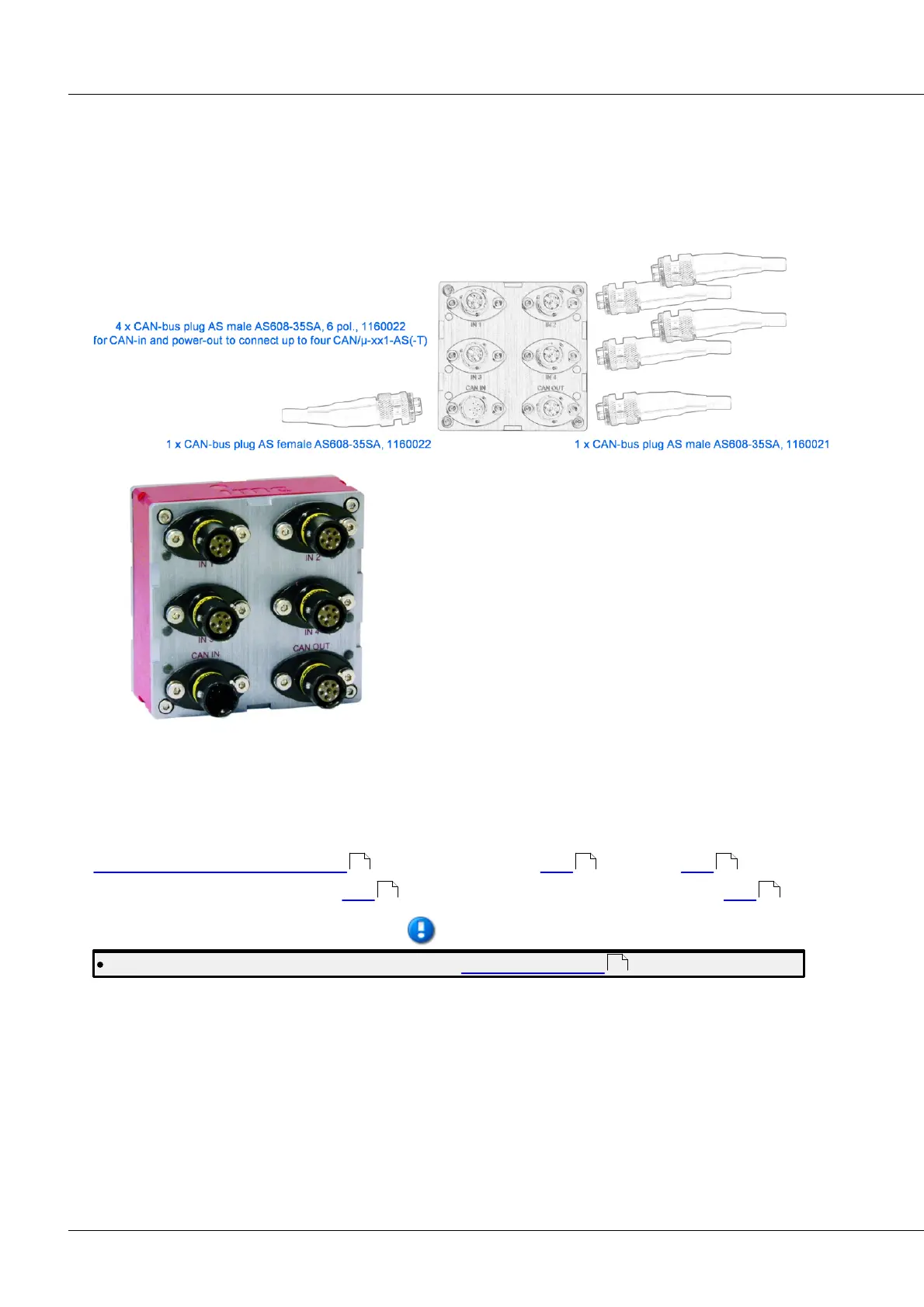
6.27 µ-CANSAS-HUB4
The imc µ-CANSAS-HUB4 serves to convert the CAN messages of up to 4 1-channel imc µ-CANSAS
modules into one or more (max. 4) new CAN messages and to transmit them via the CAN-Bus.
The imc µ-CANSAS modules are supplied with power by the imc µ-CANSAS-HUB4 via the corresponding
CAN-Bus pins.
A seperate CAN-Bus results from each connection
between a 1-channel imc µ-CANSAS module and the imc
µ-CANSAS-HUB4. The imc µ-CANSAS-HUB4 contains a
built-in terminal resistor for each terminal at which a imc
µ-CANSAS module can be connected.
Integration of the measurement modules into the system
is accomplished in the same way as for the other modules.
Depending on how many imc µ-CANSAS modules are
connected to the imc µ-CANSAS-HUB4, the imc CANSAS
user’s interface displays the corresponding amount of
channels for the respective imc µ-CANSAS-HUB4.
The channels can be sent together in one message in the customary manner or divided among multiple
messages as desired. With each imc µ-CANSAS channel having a message length of 16 bits, all 4 channels
can be sent by the HUB in one message. If a message length higher than 16 Bit (24 or 32 Bit) is set, then
the 4 channels need to be distributed over 2 messages.
Technical data imc µ-CANSAS-HUB4. CAN-Bus connector see here . Cables see here .
Sensor connector with Phoenix see here . Sensor connector with Autosport AS plug see here .
The functions of the LEDs are described in section imc CANSAS blinking codes.
517 528 530
558 561
220